Installing OEM backup cam

Disclaimer: Links on this page pointing to Amazon, eBay and other sites may include affiliate code. If you click them and make a purchase, we may earn a small commission.

MTGTS

Member
Joined
Mar 1, 2014
Posts
40
Reaction score
11
Location
Orlando
Ram Year
2014
Engine
6.7 Cummins
@MTGTS,
Yep, you only have the lock wires going forward in the 2nd picture, but you have everything else.
If you follow jeepguy1980's original instructions for the chassis harness you removed and reference the print for your truck i posted, you should be OK. But DO NOT get the pins wrong / colors mixed up since that harness is different than everyone else's and the OEM stuff.

PS: you never posted the length of that harness

That would make sense and be easy except for that the ends inside this connector are male and not female like the ones in the jeepguy harness. Suggestions?
 

Attachments

  • 20150722_092224.jpg
    20150722_092224.jpg
    87.5 KB · Views: 57

R.L.K.

Senior Member
Supporting Member
Joined
Dec 1, 2013
Posts
12,803
Reaction score
12,500
Location
Bristol , Tn.
Ram Year
2014 4X4 QC Express 6 speed auto 355 differentials
Engine
5.7 Hemi
I have had all parts put in or installed by the dealer. I have tried to repair wiring they left out. When put into reverse I get a blue screen with "check your surroundings" I can go into safety settings and change delay for camera to turn off also shows line option but won't accept changes on the display line side. The kit is the factory 82214240. I have checked all wiring and seems to be pinned properly. Does anyone have an idea if this is a flash issue or if the wiring is causing this at the BCM plug.
While your troubleshooting if you have the opportunity WITH THE NEG. TERMINAL DISCONNECTED FROM BATT. could you please put an ohm meter between the purple and yellow wires on your new OEM KIT harness and post the results ie... (open or yes there is continuity and the amount of resistance ) another member here Mpgrimm2 is constructing a schematic of the kit you have and he needs this info . Thanks !
Also , what trim is your truck ? ST. , EXPRESS , BIGHORN ect..ect .
 
Last edited:

R.L.K.

Senior Member
Supporting Member
Joined
Dec 1, 2013
Posts
12,803
Reaction score
12,500
Location
Bristol , Tn.
Ram Year
2014 4X4 QC Express 6 speed auto 355 differentials
Engine
5.7 Hemi
While your troubleshooting if you have the opportunity WITH THE NEG. TERMINAL DISCONNECTED FROM BATT. could you please put an ohm meter between the purple and yellow wires on your new OEM KIT harness and post the results ie... (open or yes there is continuity and the amount of resistance ) another men be here Mpgrimm2 is constructing a schematic of the kit you have and he needs this info . Thanks !
Also , what trim is your truck ? ST. , EXPRESS , BIGHORN ect..ect .

I doubt very seriously that the flash is the issue , you would not get the Blue screen if that was the case .
 

Mpgrimm2

Senior Member
Preferred Vendor
Military
Joined
Mar 30, 2014
Posts
6,095
Reaction score
4,174
Location
SC
Ram Year
2022 Ram 1500 (5th Gen)
Engine
5.7L
That would make sense and be easy except for that the ends inside this connector are male and not female like the ones in the jeepguy harness. Suggestions?

Yes, de-pin the short extension's extra 6 wires, leaving the 2 for the tailgate lock in both ends of the extension. Then add in jeepguy's harness to the correct end of the extension that plugs directly into i550 at the bottom of the tailgate.

* and do me a favor and get the length of jeepguy's chassis harness
* and a complete picture of the extension, and showing both ends of it as a reference to use for others later. Then a picture after you re-pin it correctly (since this will be coming up again for others, even with the OEM kit).
 
Last edited:

Mpgrimm2

Senior Member
Preferred Vendor
Military
Joined
Mar 30, 2014
Posts
6,095
Reaction score
4,174
Location
SC
Ram Year
2022 Ram 1500 (5th Gen)
Engine
5.7L
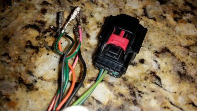
Has anyone had an issue after having camera flashed of blue screen but going into settings and being able to control delay for camera and option for lines.i have a RA2 I have checked all connections and pins other then the one a BCM. The dealer finished up wiring at PDC and BCM but left the Orange with dark blue tracer wire just hanging.

I have had all parts put in or installed by the dealer. I have tried to repair wiring they left out. When put into reverse I get a blue screen with "check your surroundings" I can go into safety settings and change delay for camera to turn off also shows line option but won't accept changes on the display line side. The kit is the factory 82214240. I have checked all wiring and seems to be pinned properly. Does anyone have an idea if this is a flash issue or if the wiring is causing this at the BCM plug.

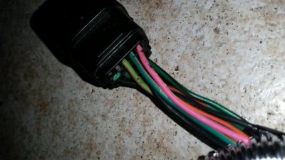
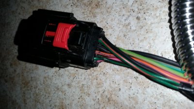
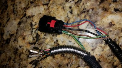
Okay , you said the dealer left the OR/ DKBL just hanging , is the purple wire soldered to this orange &Dkblue ? The yellow wire taped back ( not connected to anything ) and the Radio C1 connector has the gr/blue 31 , grey/orange 32 and bare shield 33 ?

While your troubleshooting if you have the opportunity WITH THE NEG. TERMINAL DISCONNECTED FROM BATT. could you please put an ohm meter between the purple and yellow wires on your new OEM KIT harness and post the results ie... (open or yes there is continuity and the amount of resistance ) another member here Mpgrimm2 is constructing a schematic of the kit you have and he needs this info . Thanks !
Also , what trim is your truck ? ST. , EXPRESS , BIGHORN ect..ect .

Jet,
See schematic link in post 10 as a reference.
If you paid the dealer to install the oem kit, and flash it, you should make them do the work to fix it.

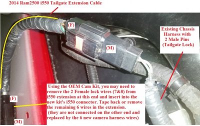
However, the Org/DK Blu wire should not be hanging or cut loose. It should be continuous, inserted into the BCM C5/E-45 pin AND have the Purple wire from the kit soldered/spliced onto it.
Even without this wire, if everything else is correct you should still have backup video on the radio.

Q: What else have you tried to 'correct' that the dealership did and why?
- go through the links in post 90, look through the install by 70chall440, and reference the kit instructions and pictures in this thread to narrow it down if you really want to do their job for them. If you read the kit instructions, it does say that the yellow wire should be tapped back (please read it), but most just connect it since there isn't any connection on the other side.

Q: What exactly are the problems you are having now and vehicle/trim level details?
 
Last edited:

R.L.K.

Senior Member
Supporting Member
Joined
Dec 1, 2013
Posts
12,803
Reaction score
12,500
Location
Bristol , Tn.
Ram Year
2014 4X4 QC Express 6 speed auto 355 differentials
Engine
5.7 Hemi
Tru that ^^^^^what mpgrimm2 said !
 

R.L.K.

Senior Member
Supporting Member
Joined
Dec 1, 2013
Posts
12,803
Reaction score
12,500
Location
Bristol , Tn.
Ram Year
2014 4X4 QC Express 6 speed auto 355 differentials
Engine
5.7 Hemi
@ Mpgrimm2, do you know where the BCM side of C5 pin 45 is going ? Does this go to the clockspring ? Is this refered to as the LINE BUS ?
 

Mpgrimm2

Senior Member
Preferred Vendor
Military
Joined
Mar 30, 2014
Posts
6,095
Reaction score
4,174
Location
SC
Ram Year
2022 Ram 1500 (5th Gen)
Engine
5.7L
@ Mpgrimm2, do you know where the BCM side of C5 pin 45 is going ? Does this go to the clockspring ? Is this refered to as the LINE BUS ?
There are not any references officially on the TechAuthority site that we as non-techs have access to that explains exactly what the Lin Bus CBC3 (C5/E-45) signal is, what it does, or how it is generated.

All we (other members) really know is that it is an output from the BCM used by the camera. We have deduced when it is left disconnected (by mistake) that it is used by the camera to generate the lines/make them turn, and further deduced that to do this the BCM uses the separate input signal from the clock spring.
 
Last edited:

R.L.K.

Senior Member
Supporting Member
Joined
Dec 1, 2013
Posts
12,803
Reaction score
12,500
Location
Bristol , Tn.
Ram Year
2014 4X4 QC Express 6 speed auto 355 differentials
Engine
5.7 Hemi
There are not any references officially on the TechAuthority site that we as non-techs have access to that explains exactly what the Lin Bus CBC3 (C5/E-45) signal is, what it does, or how it is generated.

All we really know is that it is an output from the BCM used by the camera. We have deduced when it is left disconnected (by mistake) that it is used by the camera to generate the lines/make them turn, and further deduced that to do this the BCM uses the separate input signal from the clock spring.
That is exactly what I know to be true , I've hit the same brick wall with TechAuthority myself , I badly wish I had A REAL SET OF PRINTS for my trim level on my truck , I wonder if it's a proprietary information thing with Chrysler?
My parts guy @ the local dealer printed off a set of wiring diagrams for my Bluetooth system that wer fantastic , I'll be going to see him Friday and I'm gonna see if he will print me off some for the backup camera as well for I'm tired of blind troubleshooting the fact I don't have the Active gridlines ! I feel that my connection to the clockspring though Lin BUS CBC 3 C-5 / E45 Signal is not making it to my camera /RA2 screen somehow ...?
 

Mpgrimm2

Senior Member
Preferred Vendor
Military
Joined
Mar 30, 2014
Posts
6,095
Reaction score
4,174
Location
SC
Ram Year
2022 Ram 1500 (5th Gen)
Engine
5.7L
@RLK,
I doubt it's your clockspring, or XAC Flash; likely the radio (SW update maybe) or camera itself. Bear in mind that even with a full print set, we don't know the "logic" that generates any particular signal; it's not directly wired through the BCM/computer.

Here's the i550 extension pic for those that may need it with the Kit.
Seems to be the on the 2014+ Ram2500's and possibly 3500's. Not sure why?

Will likely add it in somewhere more permanent later.
 

Attachments

  • i550 Wearout Extension.jpg
    i550 Wearout Extension.jpg
    99 KB · Views: 75
Last edited:

MTGTS

Member
Joined
Mar 1, 2014
Posts
40
Reaction score
11
Location
Orlando
Ram Year
2014
Engine
6.7 Cummins
Yes, de-pin the short extension's extra 6 wires, leaving the 2 for the tailgate lock in both ends of the extension. Then add in jeepguy's harness to the correct end of the extension that plugs directly into i550 at the bottom of the tailgate.

* and do me a favor and get the length of jeepguy's chassis harness
* and a complete picture of the extension, and showing both ends of it as a reference to use for others later. Then a picture after you re-pin it correctly (since this will be coming up again for others, even with the OEM kit).

Here are the pics of the extension and the colors of the wires that are in it. I will post more pics after I redo it.
 

Attachments

  • 20150722_164215.jpg
    20150722_164215.jpg
    95.5 KB · Views: 75
  • 20150722_164224.jpg
    20150722_164224.jpg
    97.2 KB · Views: 73

Mpgrimm2

Senior Member
Preferred Vendor
Military
Joined
Mar 30, 2014
Posts
6,095
Reaction score
4,174
Location
SC
Ram Year
2022 Ram 1500 (5th Gen)
Engine
5.7L
Here are the pics of the extension and the colors of the wires that are in it. I will post more pics after I redo it.
Don't forget to measure jeepguy1980's harness.

Sent from my Nexus 5
 

MTGTS

Member
Joined
Mar 1, 2014
Posts
40
Reaction score
11
Location
Orlando
Ram Year
2014
Engine
6.7 Cummins
I depinned these wires and then put the harness back onto the truck to make sure the tailgate lock still worked... it did.
 

Attachments

  • 20150722_165047.jpg
    20150722_165047.jpg
    102.3 KB · Views: 76

MTGTS

Member
Joined
Mar 1, 2014
Posts
40
Reaction score
11
Location
Orlando
Ram Year
2014
Engine
6.7 Cummins
This is the two harnesses combined. Jeepguys and OEM.
 

Attachments

  • 20150722_170520.jpg
    20150722_170520.jpg
    103.2 KB · Views: 91

Mpgrimm2

Senior Member
Preferred Vendor
Military
Joined
Mar 30, 2014
Posts
6,095
Reaction score
4,174
Location
SC
Ram Year
2022 Ram 1500 (5th Gen)
Engine
5.7L
Why? I've already laid it out under my truck and it is long enough
So I or someone else can possibly duplicate it in the future, I almost have all of the info I need to do it.

Sent from my Nexus 5
 
Last edited:

Mpgrimm2

Senior Member
Preferred Vendor
Military
Joined
Mar 30, 2014
Posts
6,095
Reaction score
4,174
Location
SC
Ram Year
2022 Ram 1500 (5th Gen)
Engine
5.7L
This is the two harnesses combined. Jeepguys and OEM.
You should be able to remove/de-pin the other end of the 6 unused wires from the extension cable after you are done if you want or just tape then back.

Sent from my Nexus 5
 

Jethomas

Junior Member
Joined
Jul 22, 2015
Posts
12
Reaction score
6
Location
Oshawa Ontario
Ram Year
2014
Engine
5.7
R.L.K the Orange dark blue wire was left hanging in the foot well the purple was plugged into its place already. I have checked all the wiring from camera forward to see if any bent pins. There is no sign of damage. I have tried to butt connect the Orange and purple but plan on taking it apart this weekend and solder them together. All pins at radio are on correct spot. The only connection I haven't checked is at the power distribution. The truck is an slt with locking tailgate.
 

Jethomas

Junior Member
Joined
Jul 22, 2015
Posts
12
Reaction score
6
Location
Oshawa Ontario
Ram Year
2014
Engine
5.7
Mpgrimm2 unfortunately the dealer was given the manual and had to connect the power distribution and the BCM. The had a hard time doing that so I really don't trust them.
I have double checked connection up to this point as I installed handle and all main harness to this point. The problem I have is that when put in reverse screen shows "check all surroundings" then just goes blue. The trim level of truck is slt. It had the power locking tailgate with the eight wire harness. The only other things I can think of is faulty camera or one of the factory harness wired wrong. I have gone thru entire manual three times and am going to re wire two connection that dealer did but solder them this time. Any help is much appreciated.
 

R.L.K.

Senior Member
Supporting Member
Joined
Dec 1, 2013
Posts
12,803
Reaction score
12,500
Location
Bristol , Tn.
Ram Year
2014 4X4 QC Express 6 speed auto 355 differentials
Engine
5.7 Hemi
R.L.K the Orange dark blue wire was left hanging in the foot well the purple was plugged into its place already. I have checked all the wiring from camera forward to see if any bent pins. There is no sign of damage. I have tried to butt connect the Orange and purple but plan on taking it apart this weekend and solder them together. All pins at radio are on correct spot. The only connection I haven't checked is at the power distribution. The truck is an slt with locking tailgate.
56bbab24559d16cba9f179f48a1db613.jpg

The above photo is the connector the dealer assembled @ the end of the body harness that came through the engine firewall , this connector is plugged into your radio harnes the radio harness only contains three wires ( and is assembled from the factory ) , see below for its photo , the dealer could've easily miswired at the end of the Long body harness , some guys here have done this already . Make double sure the above photo of my connector looks exactly like yours ( use the top of the connector / the lock as a reference ) if miswired here it could be a simple fix of moving wires where they are supposed to be and instant camera OR they could have damaged your radio and or camera .

Please post photos of the above connector and the BACKSIDE of you C1 Radio connector and the tailgate end of the long body harness connector .

7241d5e36f2b54c333e712977fab4046.jpg

Below is my tailgate end of the long body harness for reference.

8878e4ecbced609374395ddf055ae3de.jpg

aeda2e40be0a402355a13face2e44f29.jpg

eb33ae1957ec1c79011883f65afc6496.jpg

Another photo of the radio harness connected to the body harness
c4f4cf8195f1efb532599d38d86388bf.jpg
 
Top