Installing OEM backup cam

Disclaimer: Links on this page pointing to Amazon, eBay and other sites may include affiliate code. If you click them and make a purchase, we may earn a small commission.

R.L.K.

Senior Member
Supporting Member
Joined
Dec 1, 2013
Posts
12,803
Reaction score
12,500
Location
Bristol , Tn.
Ram Year
2014 4X4 QC Express 6 speed auto 355 differentials
Engine
5.7 Hemi
Yeh , I wish I would've printed everything for my truck when tech authority was free !
Good luck Sir !
 

TxAggie

Junior Member
Joined
Sep 27, 2013
Posts
11
Reaction score
9
Ram Year
2013
Engine
Diesel 6.7
Bump.
Hopefully one of the guys that did the full install will comment, but

- if you are ABSOLUTELY certain the BCM C5/E pin 45 wire (Lin Bus CBC3) is not populated then I believe the directions tell you to install the pre-crimped pin/wire in the cavity.
Check & recheck first! (no one else has had this happen yet. Doesn't mean it isn't possible)

- Same goes for the PDC wire. Recheck! No one that has done the full install has reported not having the 12v wire already populated.
Edit: comparing your PDC picture to RLK's (post 290), I don't see the PK/yl wire populated at C7-13 either. Don't see a few others also. But sure if there is a pin already crimped on the end of the new wire, but if you are sure of the pin location, you may be able to just install it in the connector.

(You will need to be able to disassemble/release both connector's TPA locks before you can insert the pins)

Sent from my LG G4 on Tapatalk.

Mine is a 1500 , not sure if any different?


Are you installing the oem kit ?
What two slots are you talking about ?


I've read sometimes the wire colors do not match the installation instructions.
@ the BCM C -5 connector socket # 45 if there's no wire there just insert the purple wire from the kit there ( mine had the pin pre-installed )
As far as the PDC , your wire may be a diff color , suggestion , with an ohm meter locate the Parkview 10 amp fuse socket (yours may be empty) anyway verify continuity from the fuse socket and the bottom side to verify the proper color wire to splice into for your truck .

Hope this helps

I was able to connect the purple wire. I rechecked the instructions and found different instructions for upgrading from RA1 radios. The purple wire connected into slot 45, but there were also instructions to connect the yellow wire. What is the yellow wire for, as I see most people haven't had to connect it. Those instructions also advise connecting the red power and ground to the keyed power supply in the center console. I would prefer to avoid that because I would have to uninstall my CB to do it.

I'm pretty sure the only thing I have remaining is the power connection in the PDC. Am I able to simply insert the bare wire end and it will retain it, or do I need to add the OEM wire connection? And where can I get one? I saw a post somewhere referencing how to order replacements.
 

R.L.K.

Senior Member
Supporting Member
Joined
Dec 1, 2013
Posts
12,803
Reaction score
12,500
Location
Bristol , Tn.
Ram Year
2014 4X4 QC Express 6 speed auto 355 differentials
Engine
5.7 Hemi
The yellow wire connects to the BCM C -7 FOR A MIRROR DISPLAY ONLY .
the yellow wire is unused & taped back into the harness for a radio display .
Hope this helps .
 

TxAggie

Junior Member
Joined
Sep 27, 2013
Posts
11
Reaction score
9
Ram Year
2013
Engine
Diesel 6.7
The yellow wire connects to the BCM C -7 FOR A MIRROR DISPLAY ONLY .
the yellow wire is unused & taped back into the harness for a radio display .
Hope this helps .

Yes it does thanks. Now if I can just find the post on replacement OEM pins for connecting into the standard harness.
 

R.L.K.

Senior Member
Supporting Member
Joined
Dec 1, 2013
Posts
12,803
Reaction score
12,500
Location
Bristol , Tn.
Ram Year
2014 4X4 QC Express 6 speed auto 355 differentials
Engine
5.7 Hemi
Yes it does thanks. Now if I can just find the post on replacement OEM pins for connecting into the standard harness.
Remember you will have the pins on the yellow wire and the other unused wires that go to the radio harness plug that are also unused . You could cut those ends off and splice them on the ends of other wires for use .
What do you need the pins for ? This kit is complete and ready for a 100% install if done per the instructions.
 

R.L.K.

Senior Member
Supporting Member
Joined
Dec 1, 2013
Posts
12,803
Reaction score
12,500
Location
Bristol , Tn.
Ram Year
2014 4X4 QC Express 6 speed auto 355 differentials
Engine
5.7 Hemi

TxAggie

Junior Member
Joined
Sep 27, 2013
Posts
11
Reaction score
9
Ram Year
2013
Engine
Diesel 6.7
Remember you will have the pins on the yellow wire and the other unused wires that go to the radio harness plug that are also unused . You could cut those ends off and splice them on the ends of other wires for use .
What do you need the pins for ? This kit is complete and ready for a 100% install if done per the instructions.

I had the same thought early this morning regarding the unused yellow wire and its pin. I also ordered a micro2 add-a-circuit to connect into the existing fuse location as a backup (because both the standard and mini sizes I already had don't fit %*%$%$#*^).

The power wire as supplied in the OEM kit has a bare end, no pin, as it assumes you are either tying it into the existing wire in the PDC if you have an RA2+ level configured truck, or for the instructions with the video going to the mirror (RA1) that you are tying into console power. For my application, I would prefer to tie into the PDC, just want to make sure it is a solid connection. I have already checked the fuse, it is there and power is there, just no wire yet.

So tonight, I will be cutting off the end of the yellow wire, butting it to the power supply wire and making my connection (I will visually check the pin connection in the PDC to confirm similarity first but I believe they are the same). If that fails, I will use the add-a-circuit to get power. And hopefully, I will be done.

Thanks for all the help, this thread and commentators have been very good.
 

R.L.K.

Senior Member
Supporting Member
Joined
Dec 1, 2013
Posts
12,803
Reaction score
12,500
Location
Bristol , Tn.
Ram Year
2014 4X4 QC Express 6 speed auto 355 differentials
Engine
5.7 Hemi
Anytime Sir ! Great thing about the Ram Forum is lots of great info and people here , I dally around in other auto forms and thisone is far and above others !

Post up some pics of the Final project and pics of where and discription of how you do things differently , like getting power and such ! This may help others in the future as well .
Good luck Sir !
 

TxAggie

Junior Member
Joined
Sep 27, 2013
Posts
11
Reaction score
9
Ram Year
2013
Engine
Diesel 6.7
I had the same thought early this morning regarding the unused yellow wire and its pin. I also ordered a micro2 add-a-circuit to connect into the existing fuse location as a backup (because both the standard and mini sizes I already had don't fit %*%$%$#*^).

The power wire as supplied in the OEM kit has a bare end, no pin, as it assumes you are either tying it into the existing wire in the PDC if you have an RA2+ level configured truck, or for the instructions with the video going to the mirror (RA1) that you are tying into console power. For my application, I would prefer to tie into the PDC, just want to make sure it is a solid connection. I have already checked the fuse, it is there and power is there, just no wire yet.

So tonight, I will be cutting off the end of the yellow wire, butting it to the power supply wire and making my connection (I will visually check the pin connection in the PDC to confirm similarity first but I believe they are the same). If that fails, I will use the add-a-circuit to get power. And hopefully, I will be done.

Thanks for all the help, this thread and commentators have been very good.

So cutting the yellow wire and using its connector to tie into the unpopulated PDC port was a no-go, the pins in the PDC are a larger size, or multiple sizes depending on location. So now I am waiting on delivery of my add-a-circuit.
 

R.L.K.

Senior Member
Supporting Member
Joined
Dec 1, 2013
Posts
12,803
Reaction score
12,500
Location
Bristol , Tn.
Ram Year
2014 4X4 QC Express 6 speed auto 355 differentials
Engine
5.7 Hemi
Well , you tried ... it was a good idea !
 

Mpgrimm2

Senior Member
Preferred Vendor
Military
Joined
Mar 30, 2014
Posts
6,095
Reaction score
4,174
Location
SC
Ram Year
2022 Ram 1500 (5th Gen)
Engine
5.7L
So cutting the yellow wire and using its connector to tie into the unpopulated PDC port was a no-go, the pins in the PDC are a larger size, or multiple sizes depending on location. So now I am waiting on delivery of my add-a-circuit.
Edit.

He may even have one.

Sent from my LG G4 on Tapatalk.
 
Last edited:

Mpgrimm2

Senior Member
Preferred Vendor
Military
Joined
Mar 30, 2014
Posts
6,095
Reaction score
4,174
Location
SC
Ram Year
2022 Ram 1500 (5th Gen)
Engine
5.7L
PS:
@ TxAggie
If you want more info and part numbers for modifying the official Mopar kit to be like jeepguy1980's, see...
MOPAR Backup Camera (82214240) Installed like JeepGuys
If you scroll up a few posts there, you will see the link to the schematic for jeepguy1980's harness I made with the full PN list.
(But it could bite you in the ass if you are missing the wiring between the C322 (@left wheel) and i315 (@brake pedal) connectors).

1500Ram12 may be able to tell you the pin part numbers for the PDC if they are the same as the fog light pins...
Adding foglights to 2013+ tradesman/slt


Sent from my LG G4 on Tapatalk.
 
Last edited:

TxAggie

Junior Member
Joined
Sep 27, 2013
Posts
11
Reaction score
9
Ram Year
2013
Engine
Diesel 6.7
PS:
@ TxAggie
If you want more info and part numbers for modifying the official Mopar kit to be like jeepguy1980's, see...
MOPAR Backup Camera (82214240) Installed like JeepGuys
If you scroll up a few posts there, you will see the link to the schematic for jeepguy1980's harness I made with the full PN list.
(But it could bite you in the ass if you are missing the wiring between the C322 (@left wheel) and i315 (@brake pedal) connectors).

1500Ram12 may be able to tell you the pin part numbers for the PDC if they are the same as the fog light pins...
Adding foglights to 2013+ tradesman/slt


Sent from my LG G4 on Tapatalk.

Thanks for the extra info on those connectors. I am going to save that for some of the other projects I may pursue in the future.

I was able to successfully use the add-a-circuit to tap into the fuse circuit for the rear camera power in the PDC, and success! I now have a fully functional back-up camera. I will add a few pictures and notes specific to my install on a bare bones tradesman once I get a few spare minutes.
 

DannyMK2

Senior Member
Joined
Mar 25, 2013
Posts
1,727
Reaction score
491
Location
Long Island, NY
Ram Year
2015 Power Wagon
Engine
6.4 Hemi
Danny,

Got your PM/VIN. Just checked and currently the free Chrysler TechAuthority Site is down that I would enter your VIN into to see the schematic for your particular truck. I will have to try again tomorrow or tonight after work. Unless someone has a different working link.

PS: We have been through this with a few other members and their Ram2500's (70Chall440, MTGTS, LoveRacing1988)...
either way you might as well plan on purchasing the official mopar kit for display in the radio. The cost to purchase the items you will need/may need will work out the same and if it turns out some wiring is missing you wont have to order the kit anyway. (Some of the parts in the kit CAN NOT be ordered individually). Best case scenario is that your install becomes super easy and you don't have to run/splice any wiring and end up with extra items like cptwing did. Worse case is that you have to install the entire kit.

NOTE: It is possible to verify the wiring yourself at each of the 4 connectors using the schematic in post 10 and the pictures in the linked posts. I will update with some pictures that helped the other 2500 folks in a sec.

Ref from post 10:

2013+ Factory & OEM Add-On Kit PN 82214240 schematics.png


<< What to visually check >>
- Start at the back at the tailgate (i550). The 5 factory wires from it go directly to the (C322) connector up behind the left front wheel skirting (below brake pedal).

This then passes into the cab near the brake pedal (always installed apparently).

- Next verify the 3 wires from the (i315) connector (inside cab near brake pedal) which go directly to the back of the radio's (C1) connector.

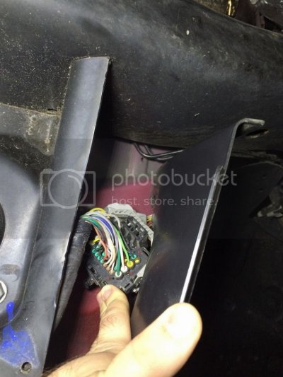
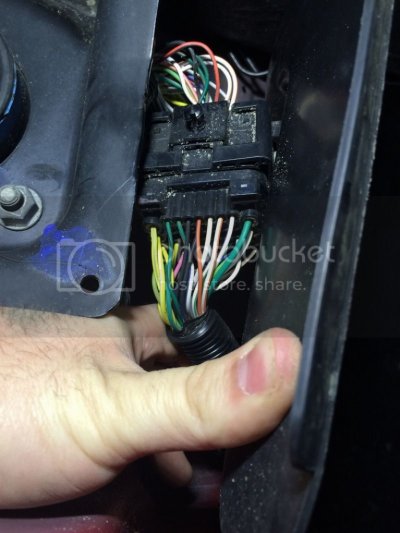
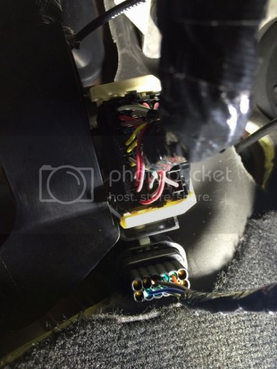
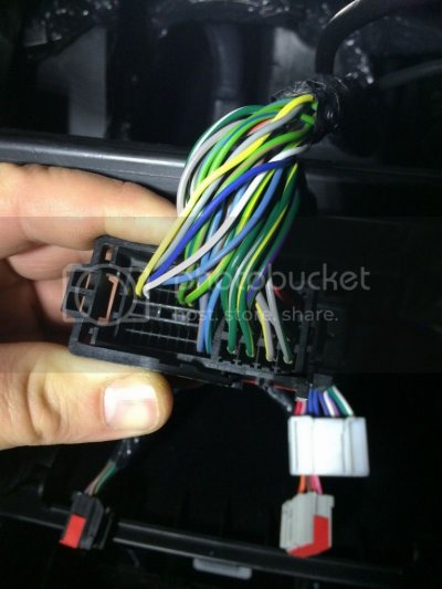
its been a while but ive finally have the opportunity to check out these connectors for the remaining wires. what i believe to have found is that i have the wires behind the front tire, i also think i have the wires near the brake pedal (considering i am looking at the correct connector), but i seem to be missing the 3 wires behind the radio. i took some pics hopefully this helps.

Behind the front tire, both sides of the connectors.
image2_zpsdbjjeswn.jpg
image3_zps1phkgxsc.jpg

Connector near brake pedal (this is to the right of the parking brake, im not 100% sure if this is the correct location)
image4_zpsxk9eplml.jpg

Behing the radio (missing the 3 wires)
image5_zpscuy6abzr.jpg

im not exactly sure what i need to do to install the OEM camera at this point. Any help is appreciated.
 

R.L.K.

Senior Member
Supporting Member
Joined
Dec 1, 2013
Posts
12,803
Reaction score
12,500
Location
Bristol , Tn.
Ram Year
2014 4X4 QC Express 6 speed auto 355 differentials
Engine
5.7 Hemi
I'm not familiar with the 2500's , but @ the radio is the same as 1500's .
@ Sockets 31 , 32 , 33 you'll just need the proper sized female pins crimped to your wires . Simply insert them fully from the rear until a light audible click , then with light pressure pull back to ensure they are locked in .
If you find it difficult to make out the 31 , 32 , 33 sockets in the radios C1 connector look at the radio side male pins , pin 31 is clearly marked .

Hope this helps!
 

DannyMK2

Senior Member
Joined
Mar 25, 2013
Posts
1,727
Reaction score
491
Location
Long Island, NY
Ram Year
2015 Power Wagon
Engine
6.4 Hemi
I'm not familiar with the 2500's , but @ the radio is the same as 1500's .
@ Sockets 31 , 32 , 33 you'll just need the proper sized female pins crimped to your wires . Simply insert them fully from the rear until a light audible click , then with light pressure pull back to ensure they are locked in .
If you find it difficult to make out the 31 , 32 , 33 sockets in the radios C1 connector look at the radio side male pins , pin 31 is clearly marked .

Hope this helps!

where are the wires? are they part of the backup camera kit? aside from the back of the radio, where do they connect to the truck?
 

R.L.K.

Senior Member
Supporting Member
Joined
Dec 1, 2013
Posts
12,803
Reaction score
12,500
Location
Bristol , Tn.
Ram Year
2014 4X4 QC Express 6 speed auto 355 differentials
Engine
5.7 Hemi
where are the wires? are they part of the backup camera kit? aside from the back of the radio, where do they connect to the truck?
If you purchase the OEM kit the kit is 100% complete with all the wires you need , to include the wires with the proper pins to plug into the radios C1 connector.
As far as " where do they connect to the truck " only 3 places other than the radio .
One wire spliced to the bottom of the PDC ( +12vdc output from the Parkview fuse)
Another to an existing ground bolt near the PDC via a ring terminal .
Another wire for the line bus CBC3 located @ socket #45 in the C-5 connector on the BCM . C-5 connector is labeled " E " on the BCM . This wire also has the proper pin installed like the radio for a simple plug n play .

Other than that , everything else is attached to the kits components ie new tailgate handle with camera , supplied harness inside the tailgate and supplied harness attaching the tailgate harness to the long body harness and the supplied long body harness . The body harness connects to the PDC , ground near PDC and the BCM'S C-5 connector , aditionally the body harness also connects to the supplied 3 wire radio harness that's supplied as well .

There's a maximum of two wires to splice / solder . One @ the fuse in the PDC and possibly @ the BCM if the socket # 45 of the C-5 connector if it's already populated , some trucks & likely yours will not be populated , in that case you'd simply plug this wire in just like @ the radio.
This kit is really simple to install and in your case could be done without splicing any wires if you used a add a wire type 10 amp fuse in the PDC and the C-5 connector really isn't populated .

You can purchase the kit @ your dealer for about $260.00 , you can sometimes find it for about $220 elsewhere .

I'd try to work a deal with the Svc manger @ your local dealer to get the XAC code Flash for FREE , if you purchase the kit from them .

You can see the complete install instructions @ post #10 here by Mpgrimm2 he has a link for the install to the radio . Here's his post #10 .
https://tapatalk.com/shareLink?url=...&share_tid=53505&share_fid=17770&share_type=t

Installing OEM backup cam


Hope this helps !
 
Last edited:

DannyMK2

Senior Member
Joined
Mar 25, 2013
Posts
1,727
Reaction score
491
Location
Long Island, NY
Ram Year
2015 Power Wagon
Engine
6.4 Hemi
If you purchase the OEM kit the kit is 100% complete with all the wires you need , to include the wires with the proper pins to plug into the radios C1 connector.
As far as " where do they connect to the truck " only 3 places other than the radio .
One wire spliced to the bottom of the PDC ( +12vdc output from the Parkview fuse)
Another to an existing ground bolt near the PDC via a ring terminal .
Another wire for the line bus CBC3 located @ socket #45 in the C-5 connector on the BCM . C-5 connector is labeled " E " on the BCM . This wire also has the proper pin installed like the radio for a simple plug n play .

Other than that , everything else is attached to the kits components ie new tailgate handle with camera , supplied harness inside the tailgate and supplied harness attaching the tailgate harness to the long body harness and the supplied long body harness . The body harness connects to the PDC , ground near PDC and the BCM'S C-5 connector , aditionally the body harness also connects to the supplied 3 wire radio harness that's supplied as well .

There's a maximum of two wires to splice / solder . One @ the fuse in the PDC and possibly @ the BCM if the socket # 45 of the C-5 connector if it's already populated , some trucks & likely yours will not be populated , in that case you'd simply plug this wire in just like @ the radio.
This kit is really simple to install and in your case could be done without splicing any wires if you used a add a wire type 10 amp fuse in the PDC and the C-5 connector really isn't populated .

You can purchase the kit @ your dealer for about $260.00 , you can sometimes find it for about $220 elsewhere .

I'd try to work a deal with the Svc manger @ your local dealer to get the XAC code Flash for FREE , if you purchase the kit from them .

You can see the complete install instructions @ post #10 here by Mpgrimm2 he has a link for the install to the radio . Here's his post #10 .
https://tapatalk.com/shareLink?url=...&share_tid=53505&share_fid=17770&share_type=t

Installing OEM backup cam


Hope this helps !

i dont have a problem buying the whole kit, but theres no need for me to install everything right? all i should need is the radio harness and the camera assembly since it appears all other wiring is present on my truck, correct? just trying to save myself from unnecessary steps.
 

R.L.K.

Senior Member
Supporting Member
Joined
Dec 1, 2013
Posts
12,803
Reaction score
12,500
Location
Bristol , Tn.
Ram Year
2014 4X4 QC Express 6 speed auto 355 differentials
Engine
5.7 Hemi
@ Danny , I doubt you have all the other required equip .

I'd purchase the whole kit and install like the instructions. That's me , but like I said I don't have a lot of knowledge on the 2500s
 

chris1965

Senior Member
Joined
Feb 23, 2016
Posts
381
Reaction score
204
Location
South Carolina
Ram Year
2014
Engine
Hemi 5.7
I was really interested in installing a oem camera, but after reading the first 3 pages, skipped a few and read the last page, I decided to buy me a wireless back up camera for $150 and done. just need it for the camper hook up anyway. :)
 
Top