How-to: 4th gen Ram/GM transmission (4L80e) swap

Disclaimer: Links on this page pointing to Amazon, eBay and other sites may include affiliate code. If you click them and make a purchase, we may earn a small commission.

charonblk07

Senior Member
Joined
Mar 14, 2013
Posts
4,056
Reaction score
2,072
Location
Calgary, Ab
Ram Year
2009
Engine
F1-A forged 349ci
This is my how-to for swapping any GM transmission into a 4th gen Ram 1500 that currently has a 545/65rfe.

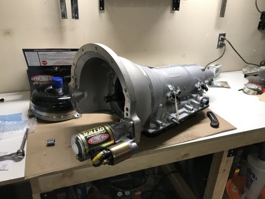
To start off with, this swap is a bit of a handful, not the cheapest solution, and there are Mopar offerings that will hold power. Given my power level, I wanted a transmission that was more reliable than the 545/65rfe, more than 3 gears, and the ability to run as an automatic or manually shifted as well. I could have done a 727 with a gear vendor overdrive or thrown the 46rh in, but I decided to do a 4L80e built to handle 1000hp with a transmission warranty. Lots of people say that the 545/65rfe is a good transmission and that they can be built to handle big power, I was one of those people who made mine last for 3 years before my built 545 finally gave out and then again only a little while later. All this happened after I swapped in my F-1A Procharger and started making a lot more HP than what I'd been making with the D-1SC previously.

This swap has the information to run ANY transmission behind the 4th gen hemi Ram and keep the PCM happy. The 545/65rfe is a revers shifting pattern, and the GM transmissions are forward shifting pattern, so the factory shifter can't be used unless you develop a lever arm system to run it. The shifter information is specific to the TCI outlaw I went with, but any aftermarket ratchet shifter will have similar setup, follow the directions of your specific shifter. I may be installing a manual into a friend's Ram in the Spring using this method, we'll see how that goes.

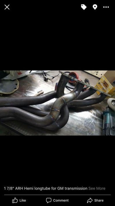
There are 2 ways to physically adapt the GM transmission to the hemi: using an adapter plate or using an adapter bellhousing. I wanted a SFI bellhousing because I plan to launch this truck under boost if I ever go to the drag strip and the SFI bellhousing is a desirable safety piece for me if the converter or flexplate ever fail. Whichever adapter method you use, there are some other considerations: long tube header clearance, starter type and size, and weight.

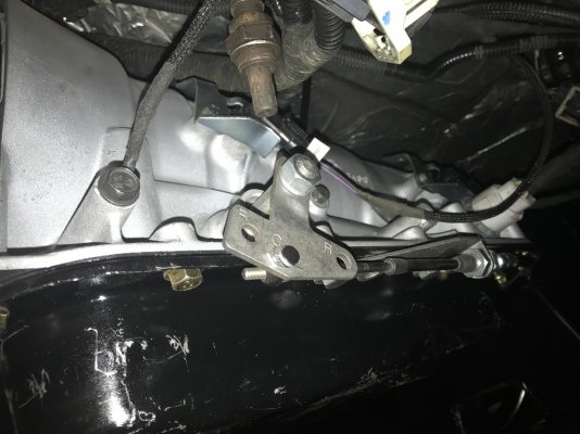
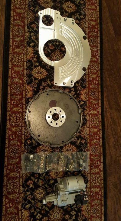
Adapter plate (photo from Jimmy Da Greek)
XcOZqhz.jpg

Adapter Bellhousing
EH4k21p.jpg

Specs on the 4L80e I used:
Weight: 178lb
Jake's Performance built Stage 4 4L80e for auto controller (no trans brake)
Trans was machined to accept a bolt-on bellhousing
Jake's Performance built single disk torque converter for 4L80e, 3400 stall, lockup capable.

The Stage 4 is warrantied to 1000 ft-lb if shifted below 7000rpm, which is good enough for me.

Here is the parts list for my swap:

GM 4L80e machined for a bolt-on bellhousing
4L80e torque converter
Reid BH060 SFI hemi adapter bellhousing (there are multiple adapter bellhousing makers)
Sonnax 3150 32T slip yoke (T3-3-2431HP)
Flexplate: JW Performance 93010-CH (you need the CH version that is bored for the spacer)
Flexplate spacer: JW Performance 80027
Starter: Powermaster XS 9513 (modification required with long tube headers)
Controller: USShift Quick4 controller w/ wiring harness
Shifter: TCI Outlaw GM 4-speed
Trans mount: Energy Suspension 3.1108G
Flexplate bolts: ARP 150-2902 (M10-1.0 x 30mm)
Dipstick: Lokar XTD-34L80FM - firewall mount dipstick
Torque converter bolts: ARP 230-7304
Driveshaft: custom length 2-piece
Intermediate cross member: custom built
Miscellaneous wiring and connectors.

Notes: 1) my truck is a quad cab 4wd w/ 6.6' bed, I'm converting to 2wd for this project. The length of the driveshaft will be different if you have a reg or crew cab. With the shorter 2wd trans I needed to install a 2-piece driveshaft and an intermediate bearing crossmember, this may not be required for other truck configurations.
2) I am using an electronic TCM, this can also be done with a manual valve body.
3) I did not get a transbrake but they can be installed as part of the 4L80e build.
4) All wiring to make the PCM happy does seem to be the same between the 4th gen trucks with either the 545rfe (5-speed) or the 65rfe (6-speed) as I've talked with a 2013 and a 2011 owners who have swapped in th350 and 200r respectively. They were extremely helpful in dealing with some electronic issues I was having.
5) I currently have to direct wire the reverse lights to the shifter's reverse switch rather than use the factory light circuit.
6) I am running an aftermarket transmission cooler, but you can install a set of braided hoses onto the factory transmission cooler hardlines and use the factory transmission cooler.


I am using the Quick4 controller but there are many options for automatic controllers from places like TCI, PCS, and others that will definitely work. I liked the Quick4 and went with it.


I am still working with the shifter electronics, I am trying to get the shifter to show up on the gauge cluster as being in P, R, N, D as I shift it. It doesn't need to do this, but I know it can be done and thought it would be a nice feature.

Background of the 545/65rfe transmission wiring:

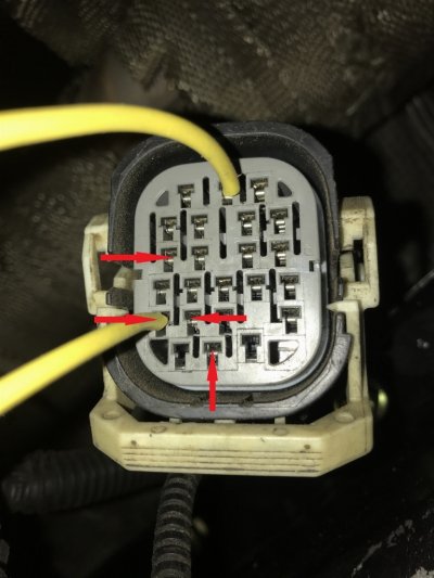
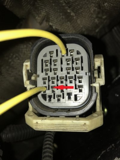
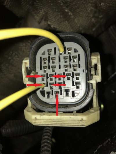
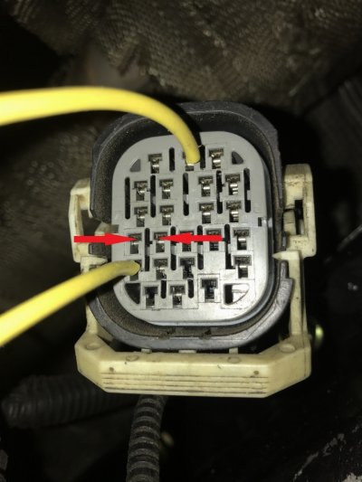
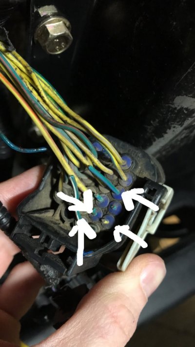
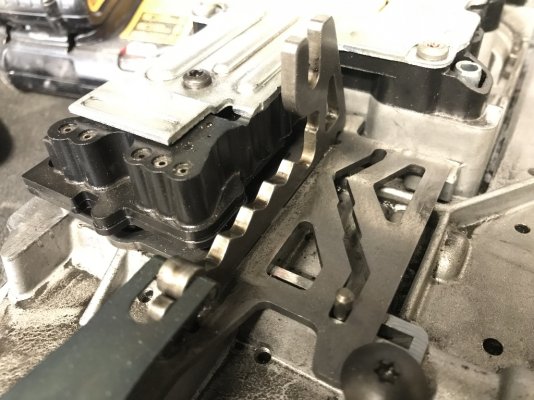
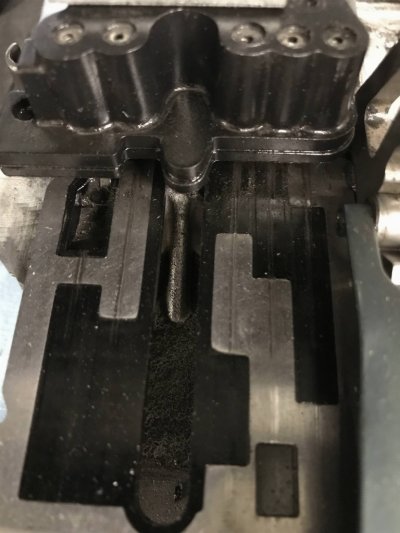
The transmission uses combinations of 5 wires to determine the gear to be displayed on the cluster. These are determined by the shifter plate on the valve body and how they ground each of the 5 circuits. I mapped the pins from the valve body with the shifter plate in each gear position to generate a pin-out map shown further in the how-to.

AcjCb7Q.jpg


jb2MQSu.jpg


With this info you can wire the PCM to show specific gears in the PCM, which I will get into more detail further down. I am providing the pin-outs for the 545rfe valve body, if you have a 65rfe please double check these are correct for yours.
 
Last edited:
OP
OP
charonblk07

charonblk07

Senior Member
Joined
Mar 14, 2013
Posts
4,056
Reaction score
2,072
Location
Calgary, Ab
Ram Year
2009
Engine
F1-A forged 349ci
Now, onto the physical swap requirements.

Step 1: Remove the old 545/65rfe; you know, the one you hate because it has left you on the side of the road more times that Taylor Swift’s sang a breakup song. You probably already either a) know how to do this because you’ve done it so many times b) you have a good shop that loves you because you’ve paid them to swap this so many times already.

Step 2: Curse and swear at the said transmission to make yourself feel better. I don’t advise kicking it like in ‘Office Space’, it hurts, especially when wearing sandals.

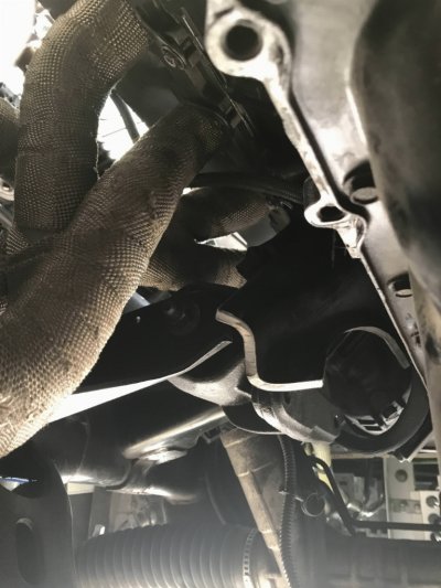
With the transmission removed, take the spacer ring off if it’s still stuck to the engine block. I ended up cutting out the old trans support that is part of the engine mount and smoothed the edges. This gets in the way of the adapter bellhousing.

wol_error.gifThis image has been resized. Click this bar to view the full image. The original image is sized 3024x4032.BC9Z2qd.jpg

Dry fit all parts to ensure proper clearances before final installation, this is a huge time saver!!!!

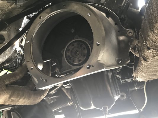
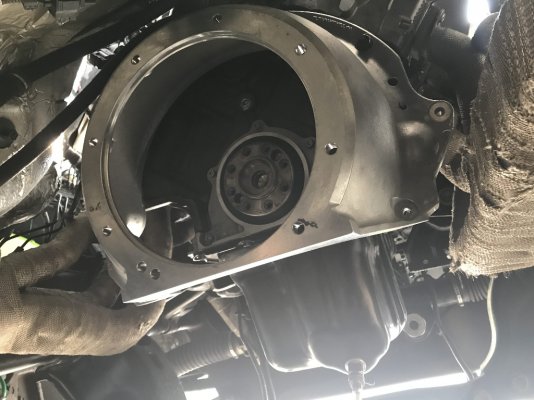
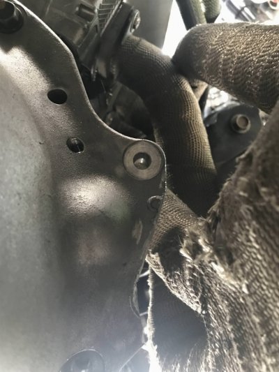
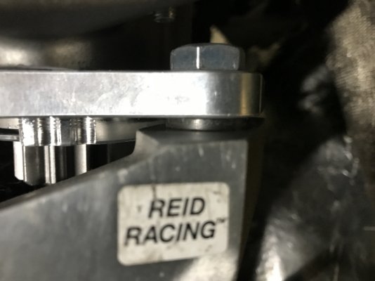
I removed the Reid adapter from the trans to do the test fitting without needing to install then whole transmission. The Reid bellhousing has a starter boss for each side since it can be used with car engines which installs the starter on the opposite side and that boss interfered with my passenger's side long tube header, so I took a chunk out of it with the grinder and the bellhousing goes ring into place. Something I found curious, the Ram uses metric bolts for damned near everything, except the bellhousing mounting bolts. Not life altering, but kept messing me up when it came to getting the correct wrench to do this which made me laugh because I’ve struggled with that every time I swapped the 545 out.

wol_error.gifThis image has been resized. Click this bar to view the full image. The original image is sized 4032x3024.EH4k21p.jpg

wol_error.gifThis image has been resized. Click this bar to view the full image. The original image is sized 3024x4032.ycsNIBD.jpg


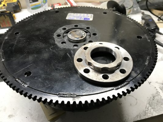
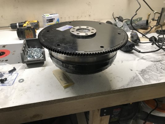
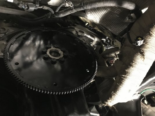
I did a brief test fit of the torque converter with the crankshaft to see if the converter snout will fit into the crankshaft output hub and it goes in with quite a bit of play in it, which is not a good thing. There needs to be an adapter spacer to do this properly and it comes with the flexplate from JW Performance. This flexplate is drilled for the Gen III hemi’s crank pattern and the 3 hole GM torque converter pattern. NOTE: Something to be aware of, the hemi crankshaft hub pattern has one hole that is slightly off the bolt circle to prevent the flexplate from being installed backwards, line up all EIGHT holes before putting bolts in.


wol_error.gifThis image has been resized. Click this bar to view the full image. The original image is sized 4032x3024.kvqmQeO.jpg


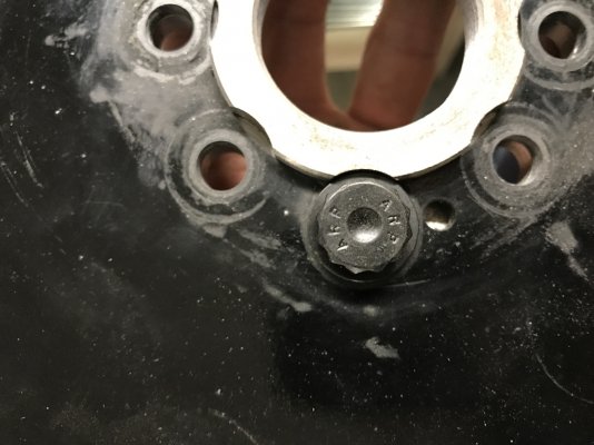
JW supplied bolts with the flexplate but they did not work as Chrysler uses an extra-fine thread pitch on the crank hub. The oem bolts aren’t long enough to be used so I had to find an alternative set of bolts and since they are extra fine thread no fastener supply company carries them as they are automotive specific. Luckily, ARP has a set of bolts for the Ford 6.4L diesel which are the proper length and pitch. There are 10 bolts and washers in the pack, but you only need 8 for the hemi, which is very handy when it comes to installing the starter.

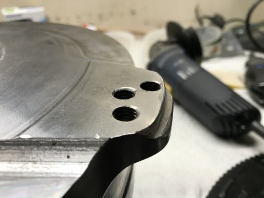
When test fitting the flexplate and torque converter I found the flexplate was sitting on the very edge of the converter’s mounting faces and leaving a large gap between the plate and mounting pad. I double checked the required orientation of the flexplate (remember that one circle that wasn’t in the standard bolt circle on the cranks hub?) and the orientation was correct. After discussing with JW, I was told to notch the mounting pads because the plate must be mounted directly to the pad. I also had to sand the snout of the torque converter to fit cleanly into the adapter spacer, it was a very tight fit so a little emery cloth helped that.


wol_error.gifThis image has been resized. Click this bar to view the full image. The original image is sized 4032x3024.3U6x1o5.jpg


Adapter from JW Performance, note the notches for the washers to clear, well thought out product.

wol_error.gifThis image has been resized. Click this bar to view the full image. The original image is sized 4032x3024.8muVtd3.jpg


Notched Torque converter

wol_error.gifThis image has been resized. Click this bar to view the full image. The original image is sized 4032x3024.XFWiuxp.jpg


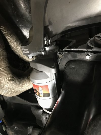
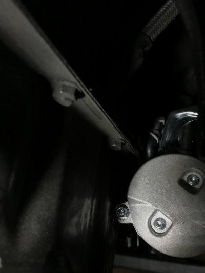
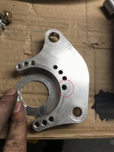
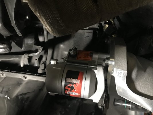
Last thing to dry fit was the starter in the bellhousing. This was the most annoying thing to do out of all the dry fitting. I started with the Powermaster 9512 and that was too long with the long tube headers so I picked up the XS 9513 which is shorter and has 3 index holes you can clock the starter to, but it turns out to have a much larger solenoid body which again interfered with the header. There are a few ways to handle this: modify the starter or modify the header. I decided to modify the starter mounting plate by lining up the starter how it wanted it to sit, marking the orientation, drilling, and taping the mounting plate and securing the starter to the plate with the supplied bolt. Another person modified the header as pictured below.

wol_error.gifThis image has been resized. Click this bar to view the full image. The original image is sized 3024x4032.YEVYn6t.jpg

It's tight, but it does fit. I removed the bolt bosses with a grinder for added clearance since I'll never be bolting the 545's flexplate dust cover back into place.

wol_error.gifThis image has been resized. Click this bar to view the full image. The original image is sized 3024x4032.zARWLhg.jpg

Lined up the starter, drew the outline, removed from the truck, laid it out and marked the hole center. Drilled and tapped the hole.

wol_error.gifThis image has been resized. Click this bar to view the full image. The original image is sized 3024x4032.qalUpFN.jpg

Adjusted starter position, no header clearance issues and easy access to the starter wiring.

wol_error.gifThis image has been resized. Click this bar to view the full image. The original image is sized 4032x3024.ZIXosVs.jpg


Here is a modified header to clear the starter (Jimmy Da Greek)
ZwcKLVD.jpg

That should be all the dry fitting required, I now moved onto installation of the shifter assembly. I did it in this order so it’s easier to pull the cables under the truck without the transmission in the way.
 
OP
OP
charonblk07

charonblk07

Senior Member
Joined
Mar 14, 2013
Posts
4,056
Reaction score
2,072
Location
Calgary, Ab
Ram Year
2009
Engine
F1-A forged 349ci
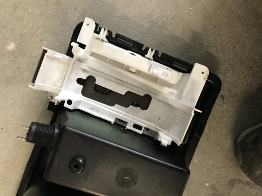
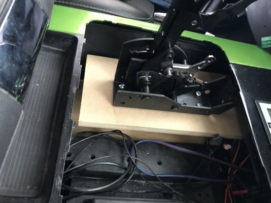
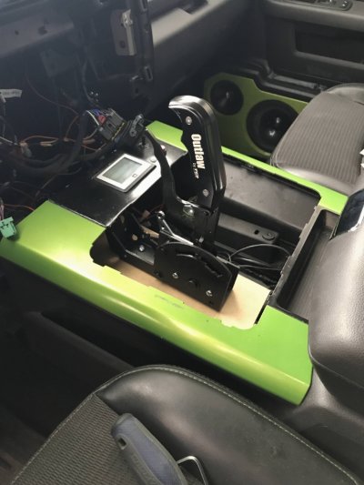
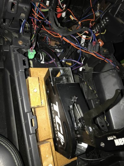
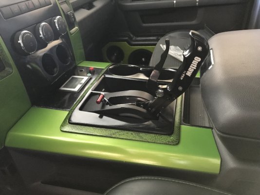
I wanted the shifter to look clean and since I have the console shifter I wanted it to look integrated. I work with wood a lot, so I went with building an MDF stand with scrap pieces that I had laying around, others have used metal to do this. Mount the shifter so it has full travel and nothing else interferes with the shifter.

I cut out the bezel of the old shifter with my Dremel, smoothed the edges, and started positioning the shifter where I thought it fit best. I built up the base as required and mounted the shifter to the MDF base. MDF is a porous material, so I coated in with fiberglass resin before installing it permanently. The base of the console is quite flat and makes this a fairly simple job to do.

qCRkLag.jpg

LJa7LBg.jpg

6gYRgVY.jpg

Ignore the rats nest of wires, I was doing multiple things at this time. It's all nicely cleaned up and loomed again.

SSgtVkA.jpg
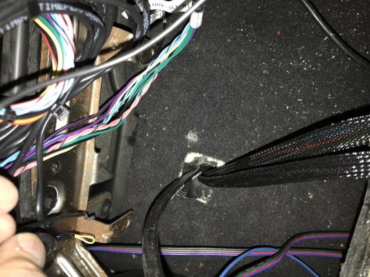
With the shifter base installed I drilled a hole in the floor of the cab, installed a grommet, and ran the cables for the shifter and the two cables for the Quick4 controller. Follow the directions for mounting the shifter cable to whatever shifter you go with.

oujCamo.jpg

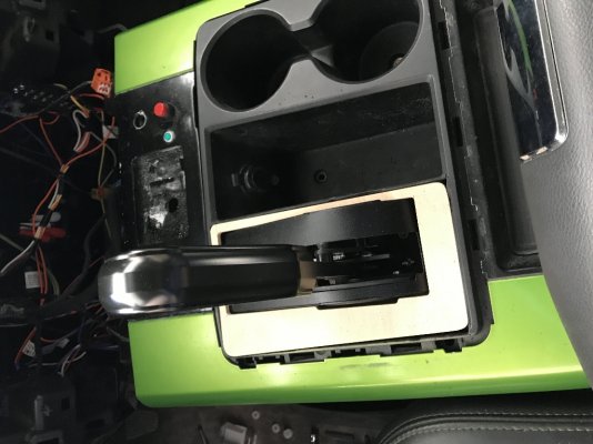
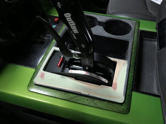
With the shifter base set up, I made a wooden insert for the console bezel, fiberglassed it in place, smoothed it out, primed and painted. I had to trim a bit off the front of the cover plate so the main console panel fit in place.


HNYCEtg.jpg
IMh8xiN.jpg


Finished product. Nice a solid, blends well. I want to make a shifter boot for it so I don't have the open hole from the cover but that's a future project.

vAxooml.jpg

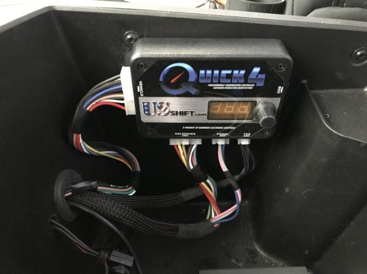
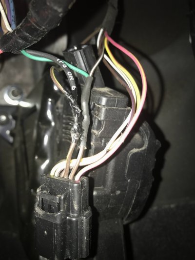
With the shifter bezel finished I installed the Quick4 controller. This came pre-loaded with a 4L80e tune based on their past experience with Jake’s transmissions so I didn’t have to do any programming work; it’s a plug and play unit for the 4L80e. I installed the controller in the console storage compartment since it can’t be installed under the hood. I wired the power and ground as instructed. One thing I will mention, their directions tell you to wire the main ground and the TPS signal ground together. DO NOT DO THIS. The Ram TPS signal is a referenced signal to the PCM and is independent of the PCM’s main ground. This caused me over a month of grief before I figured it out. Wire both the TPS signal and ground wires to the pedal assembly wiring harness. Output voltage for the pedal should read between 0.4V and 4.8V from foot off to fully depressed, you will program this into the Quick4 following their directions once the trans is installed.

c3VNDgb.jpg

Pedal wiring. I just stripped a section of wire and soldered a line onto the oem wire then covered it with liquid electric tape.

NkLQFHE.jpg
 
OP
OP
charonblk07

charonblk07

Senior Member
Joined
Mar 14, 2013
Posts
4,056
Reaction score
2,072
Location
Calgary, Ab
Ram Year
2009
Engine
F1-A forged 349ci
With everything up top done I moved to the actual trans installation.

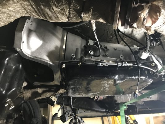
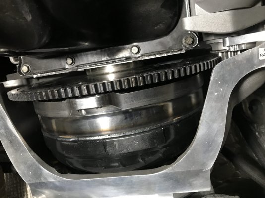
Install the Reid bellhousing onto the transmission, torque bolts to 25 ft-lb. Fill the torque converter with fluid, install the torque converter fully onto the transmission, and slide it all under the truck. Remember, when installing the torque converter, it must be fully seated in the pump, there will be 3 distinct clunks as you install it and each time the converter will push further into the transmission. Fully seated, the converter will sit about 1 inch behind the bellhousing mounting face, I test this with a straight edge and tape measure because I’m paranoid.


Ignore the starter on the trans, I was playing again.

I6xzWTT.jpg


Install the adapter spacer into the flexplate and install this onto the crankshaft hub. ARP says to use their lubricant for all ARP bolt intallations to reach proper torque spec, I use blue locktite on all flexplate bolts, but that’s just me. Torque to 70 ft-lb using a star pattern to ensure even torque is applied to the plate.

Al7HDim.jpg

j6DYzAQ.jpg


Mount the transmission to the engine block. The bellhousing should EASILY close the gap between the block, NEVER use bolts to force the bellhousing to close the gap, something is binding, and you can destroy the transmission if you do this!! Torque upper bolts to 30 ft-lb, lower bolts to 40 ft-lb. Ensure the mounting pins are lined up and the snout of the torque converter is in the adapter spacer. I left the transmission jack in place for the remainder of the installation. I also used a ratchet strap to take the weight of the trans so I could fine tune the output angle later.

9x3YhIo.jpg


80p73fi.jpg


There should be a gap between the fully seated converter and the flexplate, it must be between 0.060”-0.187”. If it’s less than this the adapter spacer is too tall or the converter has pulled out a bit, if it’s more than this then you may need to add a shim washer between the converter and flexplate when bolting it together. The amount the converter pulls back away from the transmission is critical; less than 0.060” and the pump can be impacted, greater than 0.187” and the converter can pull out of the pump.

HINT: You can’t measure the gap with a set of calipers, if you don’t have a set of feeler gauges you can use drill bits to check the gap. The gap should be larger than a 1/16” (0.0625”) bit but no bigger than a 3/16” (0.1875”) bit.
Install the flexplate to converter bolts, adding shims if required. Torque to 32 ft-lb.

iEu04JI.jpg

UriFNAi.jpg

On3lmDb.jpg
 
OP
OP
charonblk07

charonblk07

Senior Member
Joined
Mar 14, 2013
Posts
4,056
Reaction score
2,072
Location
Calgary, Ab
Ram Year
2009
Engine
F1-A forged 349ci
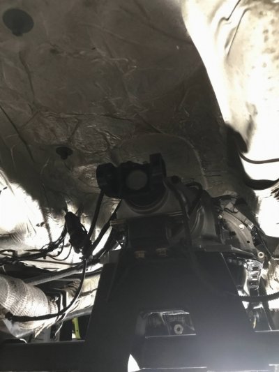
I measured the output angle of the old 545 before I removed it and the angle was -3 degrees which became my goal for the output angle of the of the 4L80e. I lifted the transmission using the transmission jack until the angle gauge on the output was at -3 degrees.

Install the transmission urethane mount to the transmission. Torque to 32 ft-lb.


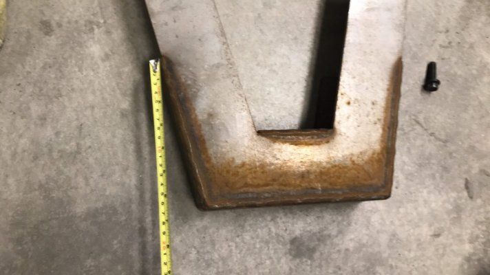
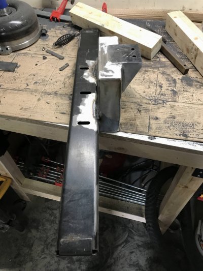
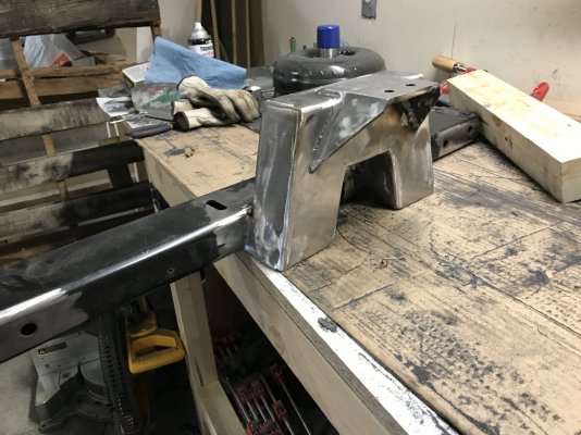
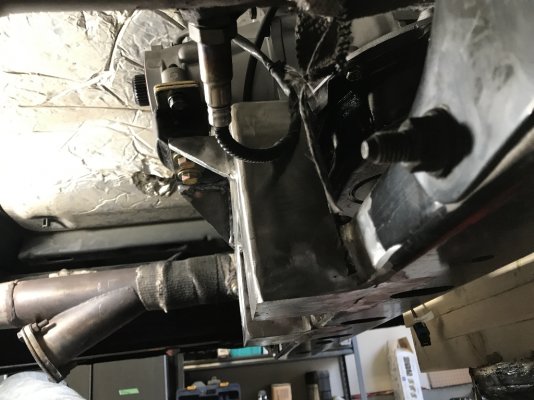
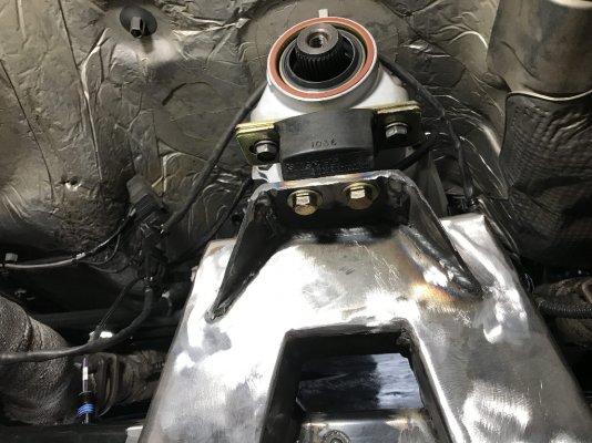
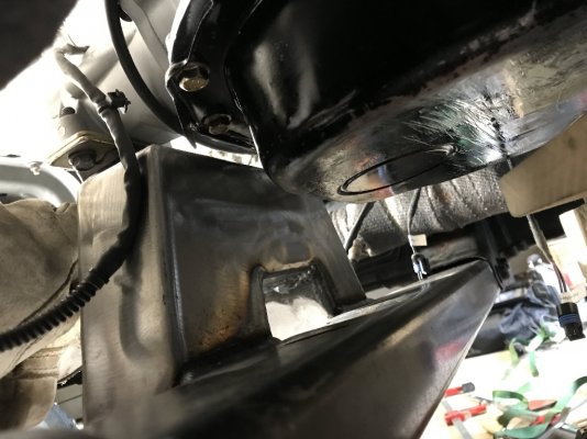
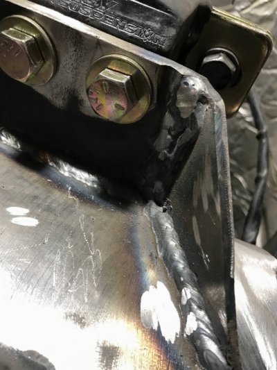
This is where fabrication skills are required because a new cross member needs to be built. The factory transmission crossmember can be used with some additions. I had an old frame notch kit laying around and decided to see if it’d work, turns out it was damned near perfect. I hacked up the kit to get all the material I needed to have a clean installation. My welding skills are not very good, I borrowed a MIG welder from a friend and tacked everything into place under the vehicle then brought it out to weld everything together. They are not pretty welds, but they have penetration into all sides and there’s nothing that a grinder, buffing wheel, and some paint can’t cover up. I was so proud that I’d made the damned thing myself; my wife also reminded me that I had set myself on fire in the process, lol.
vU19kvF.jpg

9yEyujE.jpg

OmKWnxb.jpg

nteB1xZ.jpg

Bf8eNiI.jpg

nl6rzst.jpg


Bolt the bottom of the urethan transmission mount to the new crossmember. Torque to 32 ft-lb unless the mount states differently. The transmission is now secure and the trans jack can be removed.

3sf684a.jpg


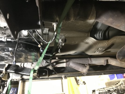
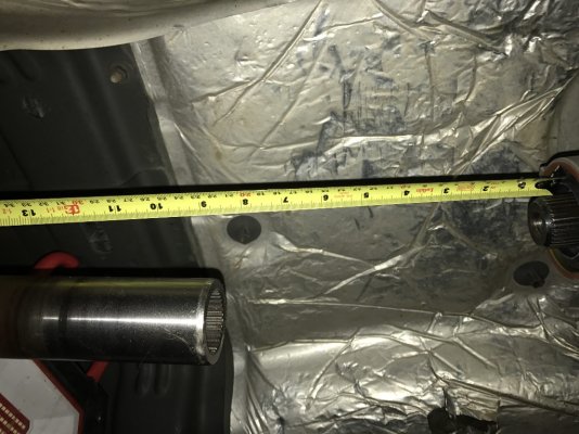
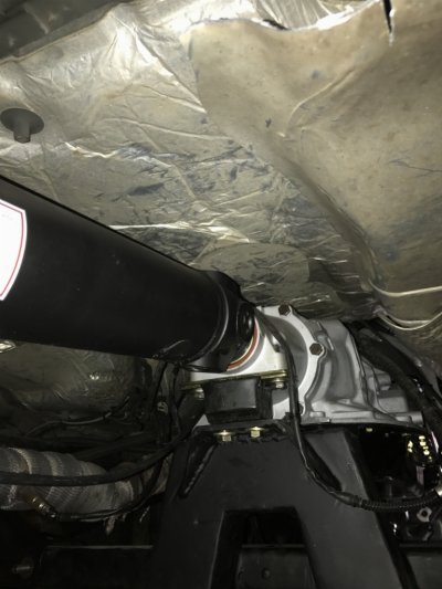
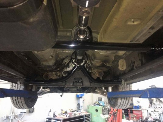
Measure the required length for the new driveshaft. I would be reusing the oem driveshaft as much as possible since I wasn’t changing the rear differential. Insert the Sonnax output yoke until bottomed out, pull it out 1 inch, and measure the distance from the differential mounting plate to the center point of the yoke’s hole. This is the required length of the new driveshaft, mine needed to be 84” long. A driveshaft that long required a 2 piece shaft to be made and an intermediate/steady bearing which my truck didn’t come with. A local driveshaft shop cut up my oem driveshaft and made a 2 piece shaft out of it. For $500 Canadian I had a new balanced 2-piece driveshaft.

VEkTdK7.jpg


Just an idea of how short the oem driveshaft was compared to the required length.

0bzlItL.jpg


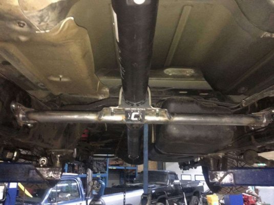
I copped out on doing the driveshaft installation myself and had a buddy’s shop do the intermediate crossmember, driveshaft alignment, install the new driveshaft, and fab up some driveshaft loops

New intermediate crossmember during fab work at CutterUp Diesel Performance.

lR1bYif.jpg

hbgWnLs.jpg

9CUg3Wd.jpg
 

Wild one

Senior Member
Joined
Jan 17, 2016
Posts
14,026
Reaction score
24,248
Ram Year
14 Sport
Engine
5.7
When said you were writing a book you weren't kidding,lol. As an observer of this swap,Kurtis has done one hell'va job,everything looks damn near like a factory install.Takes a fair bit to impress me,and i'm impressed:roflsquared:
 
OP
OP
charonblk07

charonblk07

Senior Member
Joined
Mar 14, 2013
Posts
4,056
Reaction score
2,072
Location
Calgary, Ab
Ram Year
2009
Engine
F1-A forged 349ci
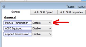
Now that the transmission was 100% physically installed I could now start playing with the electronics which would prove to be a major headache. Most of it stemmed from one bad piece of advice I received from Sharadon when I was initially discussing the swap with various people over 2 years ago when I blew the first 545. They told me in the tune to set it to ‘Manual” in the transmission tab.
DO.NOT.DO.THIS!!!
It caused me nothing but headaches. Leave the transmission tuning alone. You only need to change the rev limit in Park to match the rev limit in Drive.
VTKqTxA.jpg


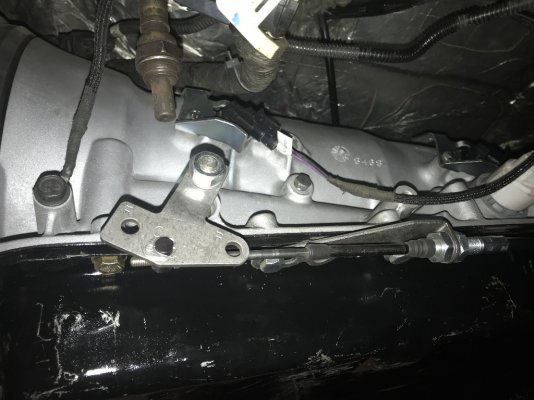
Complete the installation of the Quick 4 controller onto the transmission following the provided instructions. Complete the installation of the shifter cable to the transmission following the provided installation. You must double check the shifter cable setup before driving it so you don’t destroy the transmission, TCI provided very specific instructions for this process for their shifter.

8h9Na3w.jpg


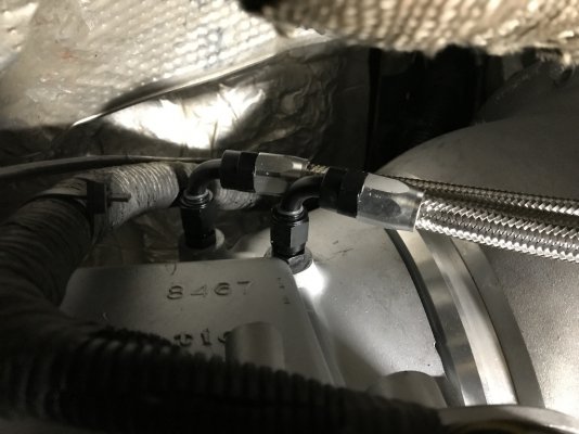
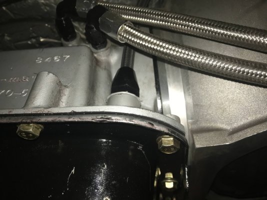
Install the transmission cooler lines. I used ¼”NPT/-6AN fittings in the transmission and ran -6AN hoses all the way to my aftermarket transmission cooler. If you want to keep the factory cooler, just cut the hard lines somewhere convenient and install a set of -6AN hardline adapters and connect the -6AN hoses to those. The 4L80e has 2 case designs based on the year made, the rear most cooler port is the return line and the forward port is the pump out. The pump out line should always be installed on the lower inlet of the cooler so it pushes air up and out of the cooler and doesn’t form an air packet which could cause over heating issues.

Nfp8nyO.jpg

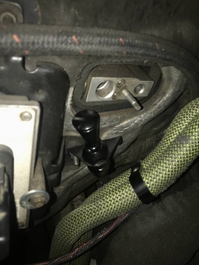
Install the dipstick into the transmission. I used a Lokar flexible dipstick to match my oil dipstick, I don’t recommend the transmission dipstick from them but couldn't find anything else that would fit my needs; it’s not easy to read and the narrow hose picks up fluid on the way in/out and gives conflicting readings, at least in my experience.I picked up the firewall mounted version as it was the longest one they had unless I custom order one.


Bh0f8lV.jpg

L1cXbDq.jpg


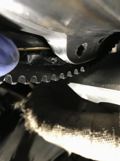
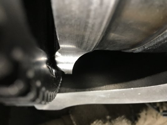
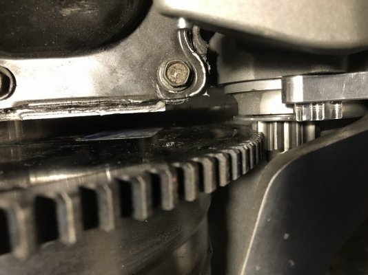
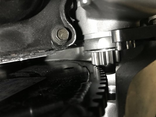
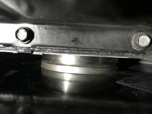
Final starter installation also needs some attention. When I first installed the starter directly into the Reid bell housing I found there was still some contact between the flexplate and the sterter's gear. This can't happen or you burn the starter out or worse, turn it into an unregulated alternator and destroy your electrical system. I ended up spacing the starter back by using the 2 extra washers left over from the ARP flexplate bolt set and I ended up with a proper clearance between the two parts.


Too much interference is a bad thing
n28Hyo1.jpg


Spaced with the washers
dk3kSMa.jpg


It's better than good, it's good enough.

HzwvB0Z.jpg


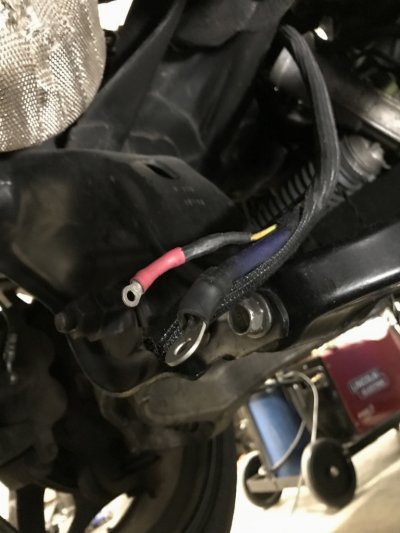
I already had a 4ga wire running my oem starter but just make sure the oem wiring is a sufficient size to safely run the draw required by the new starter. A few new crimp terminals on the wiring and it's ready to go.

cRo06W3.jpg


Now it comes to the wiring that needs to be done. I currently have the PCM staying in P and everything works fine even when moving, I want to make it show all the gears on the cluster but for the sake of this write up I am just leaving it as is for now. The safety issue with this is the truck can be started with the transmission in gear, so keep that in mind and apply at your own risk.

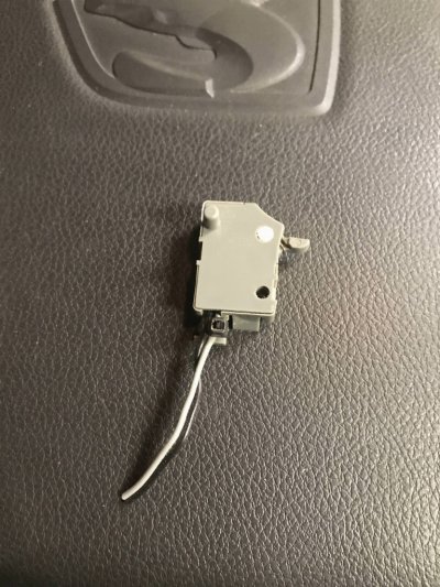
The oem console shifter has a park switch in it that must be closed when the shifter is in Park so you can turn the key all the way to remove it. I left the oem shifter wiring harness in place and just cut the switch off and wired this into the neutral switch that is part of the Outlaw shifter. When in Park or Neutral the engine can be turned off and the key can be removed but can’t when it’s in gear.

OEM neutral switch removed from wiring harness
gtIfEJ3.jpg

OEM wiring harness tied into the shifter neutral switch
ChJt29l.jpg


I am still working on getting the backup circuit to activate properly between the shifter and transmission wiring but for now I just hard wired the back up lights into the shifter switch fed by a fused power wire. At least when I put the shifter in reverse the lights come on, which is the important thing.

Now comes the fun part. Getting the PCM to recognize the gears so you can start the vehicle. Here is a guide to the pins used for each gear based on the 545’s valve body. P, R, N, and D are the same between the 545 and 65 so these are the important ones. The manual selected gears use different pin-outs and are controlled by the side-to-side movement in the oem shifter and are outside of this how-to.

Park
quLsnxA.jpg

Reverse
KpQQVNp.jpg

Neutral
cYEoOOp.jpg

Drive

iSRvSG8.jpg

Looking at the wiring harness, to get it to read as Park, you need to ground all 4 of the wires shown. Colours for my 2009 are: Grn/Ylw, Ylw/Grn, Grn/Wht, Grn/LtBl. With these 4 wires grounded my cluster shows P and the starter solenoid activates. Mine are grounded to the transmission forward of the shifter.


OSLrxKQ.jpg

4PRMqC4.jpg


Check and top up all fluids. With the tires chocked or on stands be sure that the transmission works in all gears. On the wheels, test that the transmission moves the truck forward and reverse in all gears. If it doesn’t move or acts funky in any way STOP immediately, you can easily destroy a transmission if it’s not shifting properly.

With all of this done, the truck should start up, shift gears and drive without issue. I took mine for its first drive in 1.5 years. Turns out I had overfilled the transmission and had fluid puking out the case vent. I don’t recommend the Lokar 4L80e dipstick, it’s had to read as it picks up any fluid from the narrow hose as it moves up and down. I will be installing a hose on the case vent tube and running it to an overflow can so I don't drip anything onto the street or track if it ever decides to overflow again.
 

TylerB

Senior Member
Joined
Mar 7, 2012
Posts
1,711
Reaction score
467
Location
FL
Ram Year
2011
Engine
5.7
Awesome Kurtis! Thanks for all the info!!
 

Drunken Hamster

Turncoat Ford Boi
Joined
Jul 18, 2017
Posts
1,910
Reaction score
357
Location
South Carolina
Ram Year
was 2005
Engine
was 5.7 Hemi
Is it possible to run a torque tube from the bell housing and mount the transmission further back so that the drive shaft's u-joint will attach just before the rear suspension mounts? ((this would be in an effort to improve weight distribution))

Could this also be done in the case of a manual or zf 8-speed swap?

Also, just thumbed through the post some more and noticed that the starter wasn't meshing with the flywheel. How does it start of the cogs don't mesh?

Sent from my magic 5-inch
 
Last edited:
OP
OP
charonblk07

charonblk07

Senior Member
Joined
Mar 14, 2013
Posts
4,056
Reaction score
2,072
Location
Calgary, Ab
Ram Year
2009
Engine
F1-A forged 349ci
Is it possible to run a torque tube from the bell housing and mount the transmission further back so that the drive shaft's u-joint will attach just before the rear suspension mounts? ((this would be in an effort to improve weight distribution))

Could this also be done in the case of a manual or zf 8-speed swap?

Also, just thumbed through the post some more and noticed that the starter wasn't meshing with the flywheel. How does it start of the cogs don't mesh?

Sent from my magic 5-inch

I think you'd be running into quite a few issues with a torque tube. The additional rotating mass would be one of them which could cause run on issues due to the increased inertia but I'd be more concerned with the torque converter clearance with the pump. The flexplate allows the converter to move a little bit to take up linear loading but it's still constrained to a very small distance, we're talking thousands of an inch. The clearance allowed with the converter is a 0.125" window and depending on the length of tube and the modulus of elasticity of the material, you'd have to be very careful with how the length of the tube changes during loading/unloading. If it exceeds the 0.187" you can pull the converter out of the pump or or less than the 0.060" pull back and you can impact the pump. Yes it can be done, but you have to take a lot of considerations into account to design it to work safely. There are other things you can move for safer weight distribution as well.

This could be used to install a manual transmission provided you do everything required to run a manual transmission. The 8-speed could theoretically be installed but since there are no standalone TCMs for the 8-speed transmission you'd be hard pressed to get it to work. The internal partial-TCM of the 8-speed has been the limiting factor and it's been available in performance vehicles for more than a decade and nothing has been developed to run it.

As for the starter, it has to be disengaged when the flexplate is being turned by the engine or it will act like a generator and feed electrical current back into the battery and it's unregulated so you'd be kissing the electrical system in the vehicle good bye. The starter has a plunger that's activated by the starter solenoid that moves the drive gear into engagement with the ring gear. Here's an example of what it looks like, start at 1:14.


california

Senior Member
Joined
May 10, 2013
Posts
482
Reaction score
48
Ram Year
2013
Engine
Hemi 5.7
where did you buy your kit for swap
 

Wild one

Senior Member
Joined
Jan 17, 2016
Posts
14,026
Reaction score
24,248
Ram Year
14 Sport
Engine
5.7
where did you buy your kit for swap

Kurtis is on holidays laying beside a pool right about now,lol. It might take him a bit before he checks in california
 
OP
OP
charonblk07

charonblk07

Senior Member
Joined
Mar 14, 2013
Posts
4,056
Reaction score
2,072
Location
Calgary, Ab
Ram Year
2009
Engine
F1-A forged 349ci
where did you buy your kit for swap
For a one stop shop JW Performance has the adapter bellhousing, flexplate and hub, you just need to have a 4L80e case machined for an adapter bellhousing and almost every trans builder can do this for you. I ordered mine from Jake’s performance but in the end I still had to piece some things together. The complete parts list on the first page can be ordered from anywhere if you want to do it the same way as mine, the only reason I used the Reid housing was for the SFI safety rating.


Sent from my iPhone using Tapatalk
 

Nachillo14_5.7

Junior Member
Joined
May 23, 2017
Posts
7
Reaction score
0
Ram Year
2011
Engine
Hemi 5.7
For a one stop shop JW Performance has the adapter bellhousing, flexplate and hub, you just need to have a 4L80e case machined for an adapter bellhousing and almost every trans builder can do this for you. I ordered mine from Jake’s performance but in the end I still had to piece some things together. The complete parts list on the first page can be ordered from anywhere if you want to do it the same way as mine, the only reason I used the Reid housing was for the SFI safety rating.


Sent from my iPhone using Tapatalk
How the tranny running? Is holding up well with all the power you got? Nice info! [emoji1303]


Sent from my iPhone using Tapatalk
 
OP
OP
charonblk07

charonblk07

Senior Member
Joined
Mar 14, 2013
Posts
4,056
Reaction score
2,072
Location
Calgary, Ab
Ram Year
2009
Engine
F1-A forged 349ci
How the tranny running? Is holding up well with all the power you got? Nice info! [emoji1303]

Sent from my iPhone using Tapatalk

It’s driven a grand total of 5km before being put away for the winter so I can’t pass judgement yet. I expect no issues from the trans with my current power level


Sent from my iPhone using Tapatalk
 

Rampant

Senior Member
Joined
May 21, 2016
Posts
1,895
Reaction score
1,836
Location
NJ
Ram Year
2016
Engine
392 Hemi
Great write-up and ballsy swap for sure. Kudos to you. My only question is, why didn't you stick to GM switches and work the wiring out on the other end? As a GM guy, I think it would have alleviated a whole lot of your headaches. Those switches are centric to the 4L series transmissions and were engineered to work with them from the jump. Please share your experience with this and whether the route you chose or what I suggested would work best and why. Thanks!
 
OP
OP
charonblk07

charonblk07

Senior Member
Joined
Mar 14, 2013
Posts
4,056
Reaction score
2,072
Location
Calgary, Ab
Ram Year
2009
Engine
F1-A forged 349ci
Great write-up and ballsy swap for sure. Kudos to you. My only question is, why didn't you stick to GM switches and work the wiring out on the other end? As a GM guy, I think it would have alleviated a whole lot of your headaches. Those switches are centric to the 4L series transmissions and were engineered to work with them from the jump. Please share your experience with this and whether the route you chose or what I suggested would work best and why. Thanks!

Which switches are you referring to? The PRNDL switch for the 4L80e? If so, I have one on my counter right now to start playing with to see if I can get the cluster to read correctly. I’ll be mapping the pin-out on the switch, adding the required wires and diodes, and praying to the car gods it’s as simple as that.

I still needed to map the transmission plug to know which wires I need to tie into on the truck harness because that’s the only way to get it to display on the dash; but most importantly, I needed to get the truck at least mobile so I can start using my shop space again.


Sent from my iPhone using Tapatalk
 

ric3xrt

Senior Member
Joined
Nov 26, 2016
Posts
134
Reaction score
62
Location
Trumbauersville Pa
Ram Year
2014
Engine
7.0
Great write up, don't know if it's my computer but some of the photos don't show up. My 65RFE is still holding on but I don't know how much longer I can get away with it.
Honestly I was going to shy away from a 4th gen build till I read thru your Thread here and on HTC.
 

raginglaramie

Member
Joined
Aug 30, 2017
Posts
30
Reaction score
6
Location
Edmonton,AB
Ram Year
2010
Engine
Hemi 5.7
I checked out jakes performance 4l80e and with the trans brake it requires a reverse VB. Kurtis do you know if this would work with the factory console shifter?
 
Top