
Zack02
Senior Member
- Joined
- Aug 1, 2015
- Posts
- 248
- Reaction score
- 533
- Ram Year
- 2014
- Engine
- Hemi 5.7
Please let us know how it goes. Did you have your OE link welded or are you just replacing it? Thanks
I'm just going to replace it; waited a year for a 'real' fix. I don't agree welding solves the actual issue, just prevents the nuts from coming loose (which yes, part of the issue). IMO, this is an issue with the threads. Look the conversation here from a Ram-Z forum: /threads/new-recall-for-drag-link-nuts.262611/page-2#post-2175057
omething is bothering me with the measurements in this recall.
If you read the measurement specs page 9 (5.) it says to use vernier calipers to measure and record the major outside diameter of the drag link threads 5mm from where the sleeve was installed.
It says to measure different positions and they provided me with three measurements for the inner and outer drag link. One for the sleeve.
So my values are:
25.4 sleeve largest inner diameter (step 4)
outer drag link 26.77 smallest outer diameter (step 5)
Inner drag link 26.67 smallest (step 5)
The Recall says to subtract the outer from the inner.
26.77
- 25.40
-------------
1.37mm
26.67
- 25.40
-------------
1.27mm
If this number is less than .6 drag link must be replaced, If it’s greater than .6 drag link is ok and continue. .6mm is .024”
There is one problem. These measurements are total so if we really want total thread engagement we need to divide by 2 which would give:
0.685 and 0.635mm If the spec from RAM is correct then .6 divided by 2 would give .3mm or 0.012” of threads. That seems way to little for the strength needed in this joint.
Looking at the table attached. https://mdmetric.com/tech/thddat4.htm
There is no 41mm thread. A conversion gets us to 1 1/4” X 7 thread.
The specs on that thread: http://www.carbidedepot.com/formulas-tap-standard.htm But I’m not sure how to decipher the minimum and minor axis of the thread numbers given to get the thread engagement desired.
I wonder if RAM has a typo and really needed the measurement divided by 2.
Best spec I can find is in inches for 1.25” thread bolt.
1.1233 Major screw diameter
1.0202 minor nut diameter
Subtract for .1031”
just rounding a little .10” equals 2.54mm
The minimum spec from RAM is .6mm
Something is not right. I’m no machinist so anyone have a background in threads to check my logic?
It must be bigger because if the thread was 25.4 it would not catch on the sleeve which was measured at 25.4ID
the chart I am using, https://mdmetric.com/tech/thddat8.htm
Shows
Diameter D 25.4mm
Pitch dia D2 23.774mm
Minor d3 22.148mm
Thread height H1 1.627mm
For a total interference fit full threads would be 1.627
The 25.4mm looks to be somewhere between 1 1/8 and 1 1/4"
I looked at this chart https://www.newmantools.com/tech/threadmf.htm
Closest I can find is in the 25mm range
The h3 and h1 measurements for male and female thread heights show for M1.5
h3 .920mm
h1 .812mm
But the way RAM is measuring this number should be doubled for thread height of
1.84 or 1.624
I think RAM’s minimum number of 0.6mm is way to small to keep the link together.
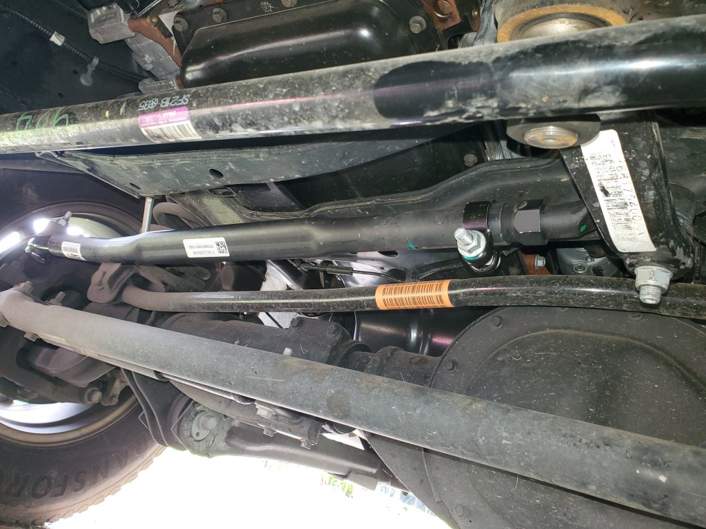
Thanks Joe, for posting a picture of the new assembly...completely different from ours.