OEM 4 Button AUX Switch Panel

Disclaimer: Links on this page pointing to Amazon, eBay and other sites may include affiliate code. If you click them and make a purchase, we may earn a small commission.

myoung84

Senior Member
Joined
Dec 2, 2010
Posts
1,899
Reaction score
319
Location
Tulsa, OK
Ram Year
2012 Power Wagon
Engine
Hemi 5.7L
I have gotten a lot of requests for help with wiring the OEM Cab and Chassis switch panel, so I figured I’d put everything in one post. For those that don’t know what it is, the switch panel installs on the lower portion of the dash and replaces the RAM insert. If you have factory heated seats then you already have a switch panel there and it cannot be replaced or modified. The new switch panel has (4) AUX buttons and cannot be modified.

Part numbers for the switch panel and pigtail wiring harness are below along with links to the online store where I purchased my parts. The wire harness is required.

5164912AC - Switch Panel
68057288AA - Pigtail Wiring

Mopar Part 5164912AC INSTRUMENT PANEL SWITCH
Mopar Part 68057288AA 8 WAY WIRING

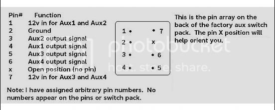
The wire harness will come with the plastic plug and 8 loose wires with metal ends crimped on. You will need to insert 7 of the 8 wires into the plug. Take note of the missing pin in the switch panel and don’t put a wire in that hole. Using the wiring diagram below, start wiring the panel once installed in the dash. Pins 1 and 7 are the 12V inputs. These should both go to a switched 12V source. You can also wire one or both wires to a constant 12V source and this would allow the switches to be operational when the truck is off. I would recommend not doing this since you would have the potential to drain the battery if you leave something on. Pin 2 will go to ground. Finally, pins 3-6 are the ground output wires for buttons 1-4. These will go to one side of the coil on a relay.
SwitchPackInstall-1_zps52c58ec8.jpg

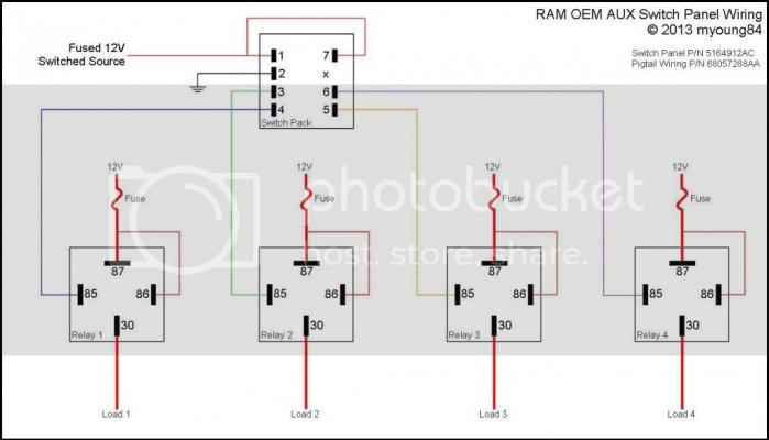
All wiring past this point will depend on what you are powering and will vary on each installation. The most common scenario such as lights would require a single relay per button. One of the output wires from the switch panel would go to the coil on the relay, either pin 85 or 86, doesn’t matter. The other side of the coil will go to a 12V source. This can be a constant source directly from the battery or you can jumper off pins 1 and 7 from the switch panel if you are installing the relays inside the truck. For my lights, I ran the output wire from the switch panel under the hood and mounted my relays near the battery.

You have the option of switching the 12V side or the ground side of your lights. I normally switch the 12V side. You would need to run the appropriate size wire from the battery, through a fuse, and to pin 87 on the relay. I will normally make a jumper wire from this pin to the 12V side of the coil on the relay, there’s no need to have separate wires ran. Then run the same size wire from pin 30 to the 12V side of your lights or other load. The ground side of you lights will go directly to ground. If you choose to switch the ground side, you will run your ground wire through pins 87 and 30 and connect the 12V side of your lights directly to the battery, through a fuse. You’ll also need to run a separate 12V wire to the coil of the relay.


Edit: Added wiring diagram to clear up some confusion.
SwitchPackWiring_zpsbd752d0e.jpg
 
Last edited:
OP
OP
myoung84

myoung84

Senior Member
Joined
Dec 2, 2010
Posts
1,899
Reaction score
319
Location
Tulsa, OK
Ram Year
2012 Power Wagon
Engine
Hemi 5.7L
Power Wagon Locker Bypass

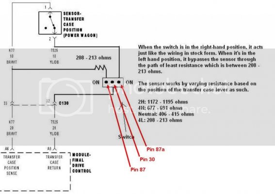
This one is specifically for the Power Wagon guys. Rather than have an ON-OFF-ON switch (SPDT) you can use a standard SPDT relay and one of the buttons. I’m not going to reinvent the wheel on the wiring of the locker bypass itself, the link to the instructions on hard wiring the bypass is on the Power Wagon Registry site is below. You can use the same instructions if you’re lucky enough to find a plug and play locker bypass harness. Rather than wire in the switch, use the following instructions to wire in the relay.

The wire colors from the PW Registry instructions didn’t match up on my truck, but it's the same process. I think the colors on mine were blue and white, with the blue one being the wire you cut. I have modified diagram below from the link on the PWR to show the instructions for using a relay instead of a switch. Run the wire from the plug side (that plugs into the transfer case) to pin 87a, then the other side of this wire to pin 30. Then splice in to the second wire on the t-case harness, wire in the resistor, and run to pin 87 on the relay. Wire the coil side of the relay they same way as above. Now, when you hit the AUX button, the relay will trigger, and the truck will think it’s in 4-low and allow the lockers to work. As long as you wired the 12V input in the switch panel to a switched source, the button will turn off each time the truck is turned off and the bypass will go back to normal mode.

Also note that trucks built after January 2012 have a new Borg Warner transfer case and the resistance values have changed. I don’t know what these new values are, but once you find out the value for 4L, then the instructions above will still work.

Power Wagon Registry - Locker Bypass Mod in 4hi, 4lo, and 2wd

locker_bypass_diagram_relay_zps7aec4c43.jpg
 
Last edited:

0212353

Vendor
Preferred Vendor
Joined
Jun 29, 2010
Posts
26,467
Reaction score
2,023
Location
Florissant, MO
Ram Year
2019 1500 Laramie Sport Crew, 2019 1500 Big Horn Sport Crew & 2016 Charger SRT Hellcat
Engine
2x 5.7L & 6.2L
Thanks for putting this up!
 

09SMOKINHEMI

Senior Member
Joined
Oct 31, 2011
Posts
2,722
Reaction score
161
Location
TEXAS
Ram Year
2009
Engine
Hemi 5.7
cool stuff.... i like mine. currently just have my hellas behind the grill connected to aux 1. hopefully some more goodies down the road.
 

jlb

Senior Member
Joined
Mar 22, 2012
Posts
1,105
Reaction score
136
Location
MT
Ram Year
2011
Engine
CTD
I thought the covered missile switches were more fun, AND less expensive lol.

Also, I tend to need more than 4...
 

Divi

Senior Member
Joined
Aug 12, 2012
Posts
153
Reaction score
47
Ram Year
2012
Engine
5.7
my wiring diagram from when i did my aux switches

396_720845827440_1612702770_n.jpg

If you search Aux switches on thbe other ram forum you will find my post with all the stuff i used.
 

Bdroddy

Member
Joined
Apr 9, 2013
Posts
70
Reaction score
25
Location
Richmond TX
Ram Year
2012
Engine
Hemi 5.7
help

I got the oem 4 switch panel and the harness from above and ran into issues. When I wire power to pin #1, ground to pin #2 and for aux 1, I put on pin #4. Nothing happened. Then I jumped power onto pin 7 to pin #1 amd then all switches worked except aux #1, it stayed lit the whole time. If I moved the to relay wire to #3 pin, then the aux #2 stayed lit the whole time. All the other switches could be turned on and off. Don't know what to do. I just put my old switch that came with my oracle lights until I could trouble shoot. I wonder if the oem 4 switch panel is bad. I double checked all connections and everything was great. Please help guys.
 

Ruiner

Senior Member
Joined
Jul 6, 2013
Posts
199
Reaction score
74
Location
Alberta
Ram Year
2012
Engine
Cummins
my wiring diagram from when i did my aux switches


If you search Aux switches on thbe other ram forum you will find my post with all the stuff i used.

I've got it bookmarked. I'll be following it closely while doing my wiring this week. I hope.

Between all of these threads I'll hopefully avoid having any issues like Bdroddy here, but that's what this forum is for, Guys helping guys fix wire their stuff.
 

Divi

Senior Member
Joined
Aug 12, 2012
Posts
153
Reaction score
47
Ram Year
2012
Engine
5.7
Soot me a PM if you have any issues or questions, my install went flawless, well minus a small power issue by using power from hte radio instead a 4awg wire from battery.
 
OP
OP
myoung84

myoung84

Senior Member
Joined
Dec 2, 2010
Posts
1,899
Reaction score
319
Location
Tulsa, OK
Ram Year
2012 Power Wagon
Engine
Hemi 5.7L
What are you feeding with the Aux 1 wire? This is a negative output and needs to go to one side of a relay coil.
 

Divi

Senior Member
Joined
Aug 12, 2012
Posts
153
Reaction score
47
Ram Year
2012
Engine
5.7
You feed Pin 85 on your relay with the output from the aux button. The output from the button is negative so you essentaily power your relay with a switched ground.
 

Bdroddy

Member
Joined
Apr 9, 2013
Posts
70
Reaction score
25
Location
Richmond TX
Ram Year
2012
Engine
Hemi 5.7
You feed Pin 85 on your relay with the output from the aux button. The output from the button is negative so you essentaily power your relay with a switched ground.

I could have screwed this up. Right now I have pin 85 grounded and the output from the switch to pin 86.
 
OP
OP
myoung84

myoung84

Senior Member
Joined
Dec 2, 2010
Posts
1,899
Reaction score
319
Location
Tulsa, OK
Ram Year
2012 Power Wagon
Engine
Hemi 5.7L
I could have screwed this up. Right now I have pin 85 grounded and the output from the switch to pin 86.

That's the problem. Change pin 85 to 12v.

Sent from my SCH-I535 using Tapatalk 4
 

Divi

Senior Member
Joined
Aug 12, 2012
Posts
153
Reaction score
47
Ram Year
2012
Engine
5.7
No 85 goes to the output from your aux button. pin 86 is 12v power.

85 needs ground to activate power to pin 87, pin 86 and 30 need constant 12v power. So when you hit your aux button t grounds the relay which completes the circut and sends 12v power out of pin 87 to the item you want power to.

The way you have it hooked up is its always on. thats why your button is always lit.
 

Divi

Senior Member
Joined
Aug 12, 2012
Posts
153
Reaction score
47
Ram Year
2012
Engine
5.7
you guys are starting to confuse me to. dont do what myoung stated, will probally melt your relay. Do what i stated above and you should be good to go.
 
OP
OP
myoung84

myoung84

Senior Member
Joined
Dec 2, 2010
Posts
1,899
Reaction score
319
Location
Tulsa, OK
Ram Year
2012 Power Wagon
Engine
Hemi 5.7L
you guys are starting to confuse me to. dont do what myoung stated, will probally melt your relay. Do what i stated above and you should be good to go.

Dude, do you actually know how a relay works?

Pins 85 and 86 are either side of a coil. It makes absolutely no difference which side gets 12v and which side gets grounded. Once those conditions are met, the coil magnetically pulls the contact from pin 87a (Normally Closed) to 87 (Normally Open).

So to reiterate, connect 12V to either pin 85 or 86, doesn't matter which. Then connect one of the AUX output wires to the other pin (85 or 86). That takes care of the coil side of the relay. Now to get power to your lights (or any other 12V load), connect 12V to either pin 87 or 30 (again, it doesn't matter), then connect the 12V side of your lights to the other pin (87 or 30). Both 12V wires need to be fused. I normally run a wire of sufficient gauge to support the load (with fuse inline) to pin 87, then jumper that to pin 85 or 86. Then run that same gauge wire to the lights or other load from pin 30.

If you have any other questions, please let me know. I've been doing this for a long time and I even went to school for Electrical Engineering, so I think I know a thing or two about electronics. ;)
 

0212353

Vendor
Preferred Vendor
Joined
Jun 29, 2010
Posts
26,467
Reaction score
2,023
Location
Florissant, MO
Ram Year
2019 1500 Laramie Sport Crew, 2019 1500 Big Horn Sport Crew & 2016 Charger SRT Hellcat
Engine
2x 5.7L & 6.2L
nah Morgan, you don't know JACK. LOL

(said by the dork in the corner that's had Morgan's help many many times on relay fun!)
 
Top