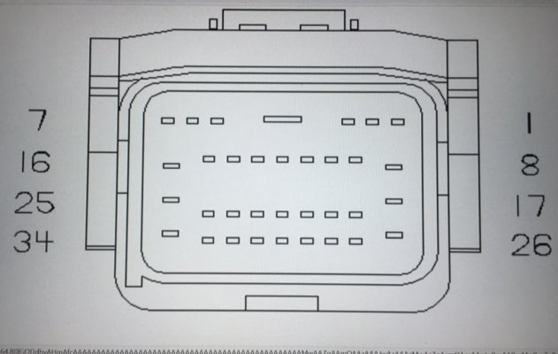
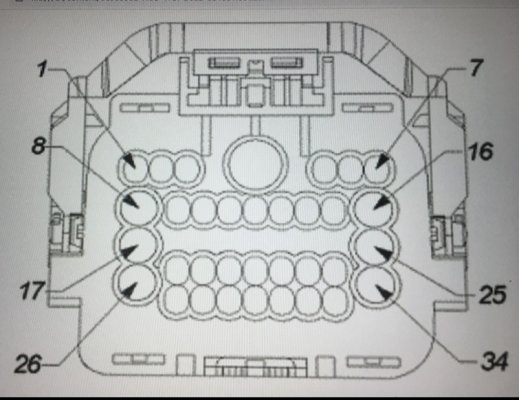
2014 1500 PCM Pin chart

Disclaimer: Links on this page pointing to Amazon, eBay and other sites may include affiliate code. If you click them and make a purchase, we may earn a small commission.

JRAM1500SC

Junior Member
Joined
Dec 22, 2023
Posts
4
Reaction score
0
Location
Bluffton SC
Ram Year
2014
Engine
5.7l
I am needing a wiring diagram, specifically with PCM pin numbers, to test fuel injector wiring. 2014 Ram Laramie 1500, 5.7L VVT MDS.
Something that i could download and/or print would be great; everything that i have found online is not legible
 

Black-Wolf

Senior Member
Supporting Member
Military
Joined
Nov 21, 2018
Posts
252
Reaction score
290
Location
North Carolina
Ram Year
2017
Engine
Hemi 5.7
I am needing a wiring diagram, specifically with PCM pin numbers, to test fuel injector wiring. 2014 Ram Laramie 1500, 5.7L VVT MDS.
Something that i could download and/or print would be great; everything that i have found online is not legible
Take a look at this - for the 8-speed transmission on a 2017 RAM - Note: most of the models don't change up the wiring between close model years. You should be able to zoom in/out using any .pdf reader. If you have a 6-speed transmission, there's a different diagram, but fuel injection pin outs is the same.
 

Attachments

  • FUEL-CONTROL-SYSTEM---5.7L---8-SPEED.pdf
    259 KB · Views: 34
OP
OP
J

JRAM1500SC

Junior Member
Joined
Dec 22, 2023
Posts
4
Reaction score
0
Location
Bluffton SC
Ram Year
2014
Engine
5.7l
That is very helpful, and simplified with just the fuel system. Thank you. But at the PCM Connectors, I've got all the pins without numbering. Is there a diagram that will show me which pin at the PCM Connector is pin 11 (K14), or pin 80 (k58), etc.?
 

Black-Wolf

Senior Member
Supporting Member
Military
Joined
Nov 21, 2018
Posts
252
Reaction score
290
Location
North Carolina
Ram Year
2017
Engine
Hemi 5.7
That is very helpful, and simplified with just the fuel system. Thank you. But at the PCM Connectors, I've got all the pins without numbering. Is there a diagram that will show me which pin at the PCM Connector is pin 11 (K14), or pin 80 (k58), etc
Unfortunately, I don't have any plug/connector diagrams.

Best thing to do is count pins with the following understanding: On a female end, Pin numbers start with #1 at the top left, and go to the right, then down, ending with the highest/last pin number at the bottom right, as you're looking at the female connector. If you're looking at the male connector, then top right is pin #1, move left to increase count, and bottom left is last pin in the connector. Best way to count them, is if it's a "balanced" connector (meaning the same number of pins in each row of pins) then just go down the right amount and count over. An example would be - say you have a connector with 4 rows, 12 pins in each row. Pin #1 is top left, pin #12 is top right. Pin #13 would be 2nd row, left most, pin #24 would be 2nd row, right most, etc. If you needed pin 33, go to row #3, and count from pin #25 over to the 8th pin. There should be 3x more pins to the right of it to verify you are on pin #33 because the last pin in that row will be #36. Once you think you've located the correct pin, check your wire color for a match - unless the factory has completely changed the wiring schematic, your wire colors should pretty much be the same as mine.
 

Mister Luck

cassis tutissima virtus
Joined
Aug 25, 2020
Posts
1,651
Reaction score
587
Location
WEST COAST
Ram Year
2016/2017
Engine
5.7 V8
3D157GYCAN IHS+
4Z910BKGROUND
5Z911BKGROUND
6D57GY/WTCAN C (+)
7NONANC
8NONANC
9NONANC
10NONANC
11D158WTCAN IHS -
12NONANC
13NONANC
14D58YLCAN C (-)
15NONANC
16A900RDFUSED B+

Pins 1 & 2 are not used
OBD2 connector all wires are 20 gauge
(2016-2017)
 
Last edited:

Mister Luck

cassis tutissima virtus
Joined
Aug 25, 2020
Posts
1,651
Reaction score
587
Location
WEST COAST
Ram Year
2016/2017
Engine
5.7 V8
1 BodyN27DB / GY 18FAN SPEED SENSOR SIGNAL
EngineNONANC
EngineN27DB / GY 18FAN SPEED SENSOR SIGNAL
2 BodyNONA 0NC
BodyT824YL / DB 18TRS PARK SIGNAL
EngineNONO 0NC
EngineT824YL / DB 18TRS PARK SIGNAL
3 BodyNONO 0NC
First 2 pins on the PCM I’ll add more maybe format on a spread sheet these are from notepad I think this is what’s required.

The below image is of a CANbus connector not a pcm connector

Face toward PCM
IMG_2763.jpeg
Back side of connector
IMG_2764.jpeg
 
Last edited:
Top