Electrical help

Disclaimer: Links on this page pointing to Amazon, eBay and other sites may include affiliate code. If you click them and make a purchase, we may earn a small commission.

RamDiver

Senior Member
Joined
Jan 23, 2022
Posts
2,139
Reaction score
3,521
Location
Marlborough, Ontario, Canada
Ram Year
2021
Engine
Hemi 5.7
OK, I've managed to make this a bit more presentable. :cool:

relay switch inverter.jpg


The constant 12V on BR/RD will keep the relay energized with the NC connected to the COM with 0VDC.

When the BR/RD toggles, momentarily removing the 12V, the relay will de-energize and provide a connection from the NO which is connected to YL/RD that will provide 12V to the common / set/coast.

Do you have any questions about how this works?

.
 
OP
OP
W

walker111

Senior Member
Joined
Apr 24, 2017
Posts
203
Reaction score
61
Ram Year
2016
Engine
6.7
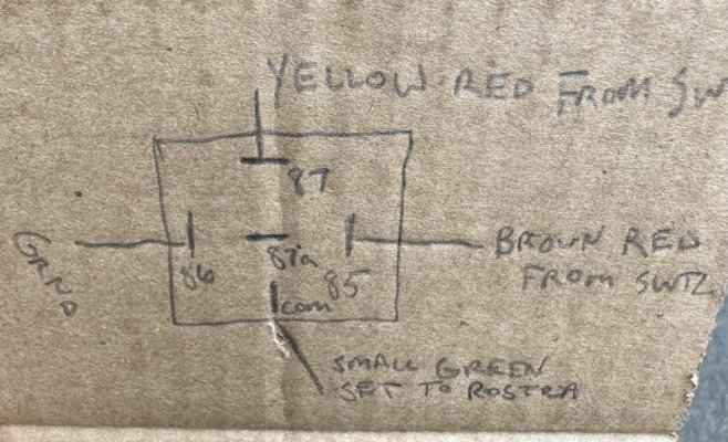
So I’ll have two wires coming from 85 and 87, correct? One set going to the switch and the other set going to the Rostra harness?
 
OP
OP
W

walker111

Senior Member
Joined
Apr 24, 2017
Posts
203
Reaction score
61
Ram Year
2016
Engine
6.7
Thank you for your help! It’s greatly appreciated! I understand your theory. I surely don’t want to fry the Rostra but I know doing thing outside of the manufacturers guidance can possibly cause problems…no worries.
 

RamDiver

Senior Member
Joined
Jan 23, 2022
Posts
2,139
Reaction score
3,521
Location
Marlborough, Ontario, Canada
Ram Year
2021
Engine
Hemi 5.7
So I’ll have two wires coming from 85 and 87, correct? One set going to the switch and the other set going to the Rostra harness?

I like to think in terms of direction, it helps me to keep the theory clear in my mind. :cool:

BR/RD is coming from the OEM switch and going to the relay coil 85. Call it the old coast/set.
The new coast/set is connected to COM on the relay. When the relay is energized, the COM is connected to the NC contact, 87A, which has no connection or 0VDC.

YL/RD is coming from the OEM switch and connected to 87, the NO contact. This is to provide a 12V pulse for the set/coast function when the relay is momentarily de-energized. This YL/RD also has to connect to the Rostra CC to provide the on/off function.

I do have some concerns that the Rostra CC employs a 10A fuse on the signal line and the OEM appears to be a 2A. Double-check those values. I'd be surprised if the signalling current is greater than 2A but I didn't design the Rostra CC. :cool:

I just looked at the Rostra CC schematic again and the 10A fuse is from the ignition, not the signalling side, so that should be just fine.


You're most welcome. Thank you for keeping my mind busy. I retired in 2016 and need to keep my mind working.

PS: the relay current capability should slightly exceed the smallest fuse value on the OEM switch signalling side. i.e if the OEM fuse is 2A, use a 3A or greater.

.

.
 
Last edited:
OP
OP
W

walker111

Senior Member
Joined
Apr 24, 2017
Posts
203
Reaction score
61
Ram Year
2016
Engine
6.7
I like to think in terms of direction, it helps me to keep the theory clear in my mind. :cool:

BR/RD is coming from the OEM switch and going to the relay coil 85. Call it the old coast/set.
The new coast/set is connected to COM on the relay. When the relay is energized, the COM is connected to the NC contact, 87A, which has no connection or 0VDC.

YL/RD is coming from the OEM switch and connected to 87, the NO contact. This is to provide a 12V pulse for the set/coast function when the relay is momentarily de-energized. This YL/RD also has to connect to the Rostra CC to provide the on/off function.

I do have some concerns that the Rostra CC employs a 10A fuse on the signal line and the OEM appears to be a 2A. Double-check those values. I'd be surprised if the signalling current is greater than 2A but I didn't design the Rostra CC. :cool:


You're most welcome. Thank you for keeping my mind busy. I retired in 2016 and need to keep my mind working.

.
Perfect! I’m looking forward to retirement in a dozen or so years. ;p
 
OP
OP
W

walker111

Senior Member
Joined
Apr 24, 2017
Posts
203
Reaction score
61
Ram Year
2016
Engine
6.7
Well, we’re definitely getting somewhere.

Cruise turns on and off with the factory switch. Brake and clutch cancel cruise.

But, the only thing I can do is accelerate by pushing both set and resume at the same time. Single button push of set does nothing. Single or holding resume does nothing.

At the kiddos soccer practice and I’ve changed the dip switches to NC switch instead of NO to see if that does anything.
 
OP
OP
W

walker111

Senior Member
Joined
Apr 24, 2017
Posts
203
Reaction score
61
Ram Year
2016
Engine
6.7
So, with the dip switches to NC on/off works, brake/clutch disengage, resume sets and accelerates. Set does nothing
 

RamDiver

Senior Member
Joined
Jan 23, 2022
Posts
2,139
Reaction score
3,521
Location
Marlborough, Ontario, Canada
Ram Year
2021
Engine
Hemi 5.7
So, with the dip switches to NC on/off works, brake/clutch disengage, resume sets and accelerates. Set does nothing

Let's investigate each individual setting, one at a time. Move the settings back to NO because that's how all the signaling should work.

If you have everything wired, including the relay as per the above drawing, you should hear the relay click as it engages when you switch the cruise on.

You should also be able to measure the COM terminal and see 0 VDC.

When you tap the set switch, the COM terminal should briefly jump to 12 VDC and then fall back to zero.

The above to measurements are with reference to (wrt) ground.

How are those actions working?

.
 
OP
OP
W

walker111

Senior Member
Joined
Apr 24, 2017
Posts
203
Reaction score
61
Ram Year
2016
Engine
6.7
It was too late to investigate last night, I’m stuck at work til tomorrow morning. I’ll work on it tomorrow.
 
OP
OP
W

walker111

Senior Member
Joined
Apr 24, 2017
Posts
203
Reaction score
61
Ram Year
2016
Engine
6.7
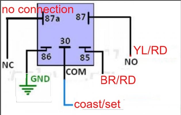
OK, I've managed to make this a bit more presentable. :cool:
View attachment 528320


The constant 12V on BR/RD will keep the relay energized with the NC connected to the COM with 0VDC.

When the BR/RD toggles, momentarily removing the 12V, the relay will de-energize and provide a connection from the NO which is connected to YL/RD that will provide 12V to the common / set/coast.

Do you have any questions about how this works?

.


So I think my electric skills are getting the best of me. Currently my relay doesn’t have anything connected to 87a.
 
OP
OP
W

walker111

Senior Member
Joined
Apr 24, 2017
Posts
203
Reaction score
61
Ram Year
2016
Engine
6.7
So I think my electric skills are getting the best of me. Currently my relay doesn’t have anything connected to 87a.

Rereading your post 87a should be going to the Rostra. What goes on the 30/com terminal?
 

RamDiver

Senior Member
Joined
Jan 23, 2022
Posts
2,139
Reaction score
3,521
Location
Marlborough, Ontario, Canada
Ram Year
2021
Engine
Hemi 5.7
Rereading your post 87a should be going to the Rostra. What goes on the 30/com terminal?

Look at the picture in post 21 and read the detailed explanation in post 24.

Terminal 87A (NC) has large red type that says no connection. In the explanation, it says no connection 0VDC.

The NC terminal is connected to the COM terminal when the relay is energized to provide the steady low signal state that the Rostra requires.

The COM terminal is the new set/coast terminal for the Rostra after the relay has fixed the signal to be low (0 VDC) for no action and high (12 VDC) to signal a change.

Is that too much detail and making it more complicated?

.
 
OP
OP
W

walker111

Senior Member
Joined
Apr 24, 2017
Posts
203
Reaction score
61
Ram Year
2016
Engine
6.7
Look at the picture in post 21 and read the detailed explanation in post 24.

Terminal 87A (NC) has large red type that says no connection. In the explanation, it says no connection 0VDC.

The NC terminal is connected to the COM terminal when the relay is energized to provide the steady low signal state that the Rostra requires.

The COM terminal is the new set/coast terminal for the Rostra after the relay has fixed the signal to be low (0 VDC) for no action and high (12 VDC) to signal a change.

Is that too much detail and making it more complicated?

.
Sorry. I originally took no connection as nothing connected to that terminal.
 
OP
OP
W

walker111

Senior Member
Joined
Apr 24, 2017
Posts
203
Reaction score
61
Ram Year
2016
Engine
6.7
I am unfortunately still lost in this. I get what it’s doing, just lost how to hook it up.

I have yellow/red from switch into 87, also a wire from that same terminal to the Rostra harness.

Terminal 86 is grounded

Brown red from switch to 85

When you say

“The NC terminal is connected to the COM terminal when the relay is energized to provide the steady low signal state that the Rostra requires.”

Is the NC connected to COM in the relay? Or by a jumper wire?
 
OP
OP
W

walker111

Senior Member
Joined
Apr 24, 2017
Posts
203
Reaction score
61
Ram Year
2016
Engine
6.7
You might’ve thought I was joking when I said I had 2nd grade electric skills.
 

RamDiver

Senior Member
Joined
Jan 23, 2022
Posts
2,139
Reaction score
3,521
Location
Marlborough, Ontario, Canada
Ram Year
2021
Engine
Hemi 5.7
The relay is a simple switch that is opened or closed by applying a voltage across the coil, terminals 85 & 86.

Closed is the same as connected or on.
Open is the same as disconnected or off.

Think of the relay of an on/off switch.

We're using the 12 V from the truck's set/coast switch on terminal 85 to energize the relay or close a circuit.

Terminal 86 should be connected to ground so that we have a 12V potential from 85 to 86. This is how the relay is energized.

85 & 86 are the coil that makes the switch open or close.

When the relay is energized, the normally closed (NC) terminal 87a is connected to the COM terminal, also know as the common.

We have nothing connected to 87a, therefore the COM terminal will be at 0V.

The COM terminal is connected to the set/coast on the Rostra.

Try reading each paragraph while viewing the relay diagram and working to understand each, before moving on.

All together, it might sound a bit confusing but in smaller bits might be more clear.
.
 
OP
OP
W

walker111

Senior Member
Joined
Apr 24, 2017
Posts
203
Reaction score
61
Ram Year
2016
Engine
6.7
So with the relay hooked up correctly. I’m still getting 12v. When I press set, it drops to 0
 
Top