You are using an out of date browser. It may not display this or other websites correctly.
You should upgrade or use an alternative browser.
You should upgrade or use an alternative browser.
Electrical help
- Thread starter walker111
- Start date
Disclaimer: Links on this page pointing to Amazon, eBay and other sites may include affiliate code. If you click them and make a purchase, we may earn a small commission.
walker111
Senior Member
- Joined
- Apr 24, 2017
- Posts
- 203
- Reaction score
- 61
- Ram Year
- 2016
- Engine
- 6.7
Let's investigate each individual setting, one at a time. Move the settings back to NO because that's how all the signaling should work.
If you have everything wired, including the relay as per the above drawing, you should hear the relay click as it engages when you switch the cruise on.
You should also be able to measure the COM terminal and see 0 VDC.
When you tap the set switch, the COM terminal should briefly jump to 12 VDC and then fall back to zero.
The above to measurements are with reference to (wrt) ground.
How are those actions working?
.
The relay only clicks when I hit set. Nothing when I turn it on/off
COM has 12v
RamDiver
Senior Member
- Joined
- Jan 23, 2022
- Posts
- 2,138
- Reaction score
- 3,521
- Location
- Marlborough, Ontario, Canada
- Ram Year
- 2021
- Engine
- Hemi 5.7
The relay only clicks when I hit set. Nothing when I turn it on/off
COM has 12v
That's interesting.
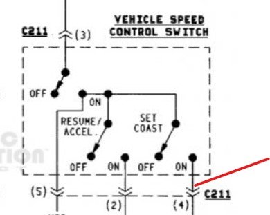
This would suggest that the BR/RD is normally low and goes high when you press the set button, unlike the diesel supplement drawing in post #15.
The BR/RD is connected to the relay coil and if it was normally high (12VDC), when the CC was activated, the relay would be energized. This is according to the diesel supplement drawing.
In your posts, 1 & 9, all of the OEM switches are normally open (0VDC).
In your post 15, with the diesel supplement, BR/RD is connected to the OEM set/coast switch which is normally high (12VDC).
The circuit design is based on the diesel supplement drawing. If that drawing is wrong, so is the circuit design.
This should be a lesson for us both, don't trust any manual or word of mouth. Test the circuit first and you will know the true state.
Disconnect C211 and measure the voltage on the switch side of pin 4.
I'm guessing you will see 0VDC until you press the set button, then 12VDC.

.
RamDiver
Senior Member
- Joined
- Jan 23, 2022
- Posts
- 2,138
- Reaction score
- 3,521
- Location
- Marlborough, Ontario, Canada
- Ram Year
- 2021
- Engine
- Hemi 5.7
Br/rd definitely has power at the switch, hard to think I have a bad relay but I’ll try another relay.
Wait!
Let's discuss this before you take any action.
If BR/RD is normally at 12VDC and it is connected to the relay terminal 85, the relay should be energized.
You say the relay isn't energized until you press the set button yet the BR/RD has 12VDC.
Those 2 conditions are contradictory if the wiring to the relay is the same as the drawing.
.
Last edited:
RamDiver
Senior Member
- Joined
- Jan 23, 2022
- Posts
- 2,138
- Reaction score
- 3,521
- Location
- Marlborough, Ontario, Canada
- Ram Year
- 2021
- Engine
- Hemi 5.7
Did you see my drawing? It’s exactly like that, which is like yours.
OK, you say that BR/RD has 12V at the switch, then, you should have 12V at relay terminal 85 because the BR/RD is connected there.
Do you agree? Have you measured 12V at both the switch end and at relay terminal 85?
Are you using the same ground reference for the negative test lead on the multimeter?
.
Joseph Godvin
Member
My opinion is your way over thinking this........not gonna end well !!! Mechanic for over 40 years.....Not close to being a "parts changer" !!!!
walker111
Senior Member
- Joined
- Apr 24, 2017
- Posts
- 203
- Reaction score
- 61
- Ram Year
- 2016
- Engine
- 6.7
Great advice. Wait…there wasn’t any.My opinion is your way over thinking this........not gonna end well !!! Mechanic for over 40 years.....Not close to being a "parts changer" !!!!
walker111
Senior Member
- Joined
- Apr 24, 2017
- Posts
- 203
- Reaction score
- 61
- Ram Year
- 2016
- Engine
- 6.7
Back at work, I’ll confirm tomorrow morning.OK, you say that BR/RD has 12V at the switch, then, you should have 12V at relay terminal 85 because the BR/RD is connected there.
Do you agree? Have you measured 12V at both the switch end and at relay terminal 85?
Are you using the same ground reference for the negative test lead on the multimeter?
.
walker111
Senior Member
- Joined
- Apr 24, 2017
- Posts
- 203
- Reaction score
- 61
- Ram Year
- 2016
- Engine
- 6.7
Yes I have 12v at the switch and 85. When I press set, COM is at 0. We want the opposite, correct?OK, you say that BR/RD has 12V at the switch, then, you should have 12V at relay terminal 85 because the BR/RD is connected there.
Do you agree? Have you measured 12V at both the switch end and at relay terminal 85?
Are you using the same ground reference for the negative test lead on the multimeter?
.
Last edited:
walker111
Senior Member
- Joined
- Apr 24, 2017
- Posts
- 203
- Reaction score
- 61
- Ram Year
- 2016
- Engine
- 6.7

2nd Gen Ram Cummins 12v NV4500 Rostra Cruise Control using stock steering wheel switch
Rostra CC 250-1223 using the stock 94 control switch. Relay used to give SET power only when pressed.
RamDiver
Senior Member
- Joined
- Jan 23, 2022
- Posts
- 2,138
- Reaction score
- 3,521
- Location
- Marlborough, Ontario, Canada
- Ram Year
- 2021
- Engine
- Hemi 5.7
@RamDiver what do you think of that relay configuration?
You have made a couple of changes to the original design I presented but these changes have the same end result, so, you're good to go.
For instance, you switched the ground & BR/RD positions on the relay coil which truly makes no difference to the functionality of the relay. You still get a 12V potential across the coil.
I would suggest you draw out a schematic for the final build and include crib notes such as voltage measurements and your understanding of the relay action. This way, if you are required to troubleshoot any faults in the future, you will have much less grief.
Congrats, you made it work in the fashion you desired.
.
walker111
Senior Member
- Joined
- Apr 24, 2017
- Posts
- 203
- Reaction score
- 61
- Ram Year
- 2016
- Engine
- 6.7
Thanks a bunch for your help!You have made a couple of changes to the original design I presented but these changes have the same end result, so, you're good to go.
For instance, you switched the ground & BR/RD positions on the relay coil which truly makes no difference to the functionality of the relay. You still get a 12V potential across the coil.
I would suggest you draw out a schematic for the final build and include crib notes such as voltage measurements and your understanding of the relay action. This way, if you are required to troubleshoot any faults in the future, you will have much less grief.
Congrats, you made it work in the fashion you desired.
.
I do understand 85 and 86 make the circuit, I was just switching things back and forth to get the 0v at rest, and the 12v when pressing the SET button.
I guess all I needed to do is get the yl/rd to COM.
I’ve drawn out the schematic in the record book, cleaned it all up and have everything back together.
Thanks again for all of your help/knowledge and patience with my electrical skills. I definitely learned a bit more about relays.
walker111
Senior Member
- Joined
- Apr 24, 2017
- Posts
- 203
- Reaction score
- 61
- Ram Year
- 2016
- Engine
- 6.7
My opinion is your way over thinking this........not gonna end well !!! Mechanic for over 40 years.....Not close to being a "parts changer" !!!!
@Joseph Godvin
Ended up exactly how I wanted it. I’ll end with modifying my original statement about “most” (NOT ALL) mechanics.
“For what? Most mechanics are parts replacers or they lack the ability to think outside of what the manufacturer designed. There are a plethora of folks on the forums who are great with outside the box electrics.
My cruise control works fine as the truck sits right now. I’m only thinking outside the box to see if it can work with the stock dodge switch. What are forums for?
You seem to be at your “wits end” so go take your truck to a mechanic. Mine works and functions great.”
RamDiver
Senior Member
- Joined
- Jan 23, 2022
- Posts
- 2,138
- Reaction score
- 3,521
- Location
- Marlborough, Ontario, Canada
- Ram Year
- 2021
- Engine
- Hemi 5.7
Thanks a bunch for your help!
I do understand 85 and 86 make the circuit, I was just switching things back and forth to get the 0v at rest, and the 12v when pressing the SET button.
I guess all I needed to do is get the yl/rd to COM.
I’ve drawn out the schematic in the record book, cleaned it all up and have everything back together.
Thanks again for all of your help/knowledge and patience with my electrical skills. I definitely learned a bit more about relays.
You're most welcome, glad I could help.
The relay is just like a remote control switch using 12V to open or close the switch. It doesn't matter too much in some instances, which end of the switch is connected to the wire coming or going on the switch side. You're still successfully opening or closing the circuit.
It's similar to the coil connections, at least in this instance. As long as you have a 12V potential across the coil, it doesn't much matter which side is ground or 12V.
Now you should understand how we can use low-current switches to control high-current devices. The relay coil doesn't use much current, so a small, low-current switch can be used to drive a high-current circuit like halogen headlights or a compressor.
I wouldn't advise changing anything with your wiring if everything works correctly.
.
Similar threads
- Replies
- 1
- Views
- 241
- Replies
- 0
- Views
- 1K
- Replies
- 6
- Views
- 2K
Latest posts
-
INFO - 2013-2018 8.4A /AN FW Notes (RA3/VP3-NA & RA4/VP4-NA & UAx)
- Latest: OasisNinjaBat
-
-
-
-
Staff online
-
G-Ride990Administrator

