Brake lights work opposite of normal, but why wouldn't they? Its a Chrysler, of course...

Disclaimer: Links on this page pointing to Amazon, eBay and other sites may include affiliate code. If you click them and make a purchase, we may earn a small commission.

ConorToot

Member
Joined
Jan 13, 2023
Posts
52
Reaction score
21
Location
Houston, Texas
Ram Year
2012
Engine
4.7L
Okay, so I'm pretty fed up with learning how to be my own mechanic, but with owning this truck, I have to be or I would be broke from the expense. Actually, with all of the crap I've had to replace and with two things breaking before I fix one previous designed defect, I'm already broke.
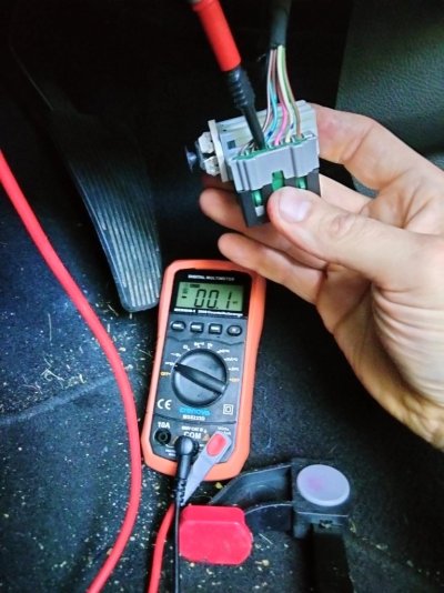
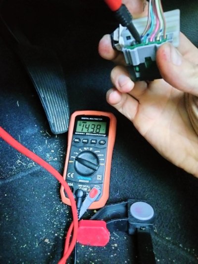
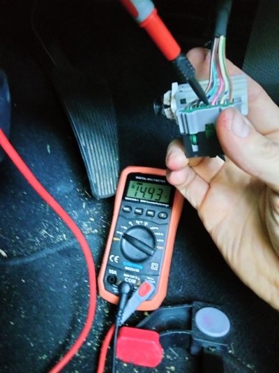
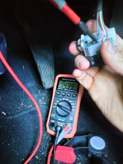
Now, this is a new twist. I've already twice replaced my "stop lamp switch" as the Chrysler hacks call it. I got a third one to try and make sure I've covered everything to correct my C121E error that has prevented me from using my cruise control for the last year. I've bled 10 gallons of brake fluid trying to find some mysterious air pocket. I've replaced all four brake calipers (discs with them). All of the speed sensors were thoroughly checked and if you want the graphs to prove I've checked, I'll set up a drive of a couple hundred recordings that prove the wheel speed sensors and tone rings are fine. The ABS works, I've tested, tested, tested, tested and done everything but replace that because, well, I can't find any new ones for less than $400. I'm not spending $400 to replace something that works. So, I went with the brake light switch or "stop lamp switch" if you will.
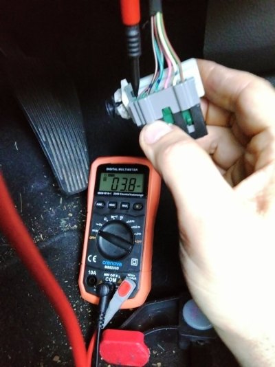
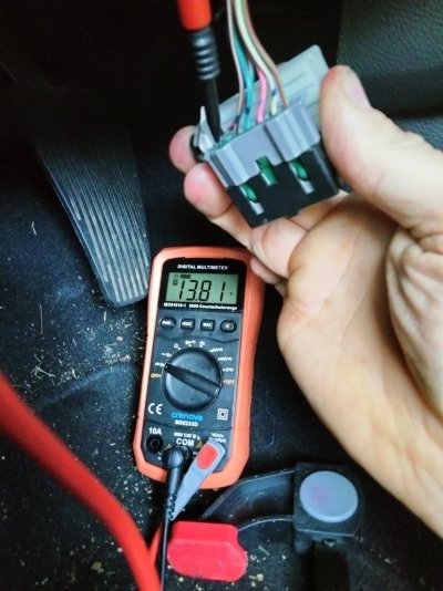
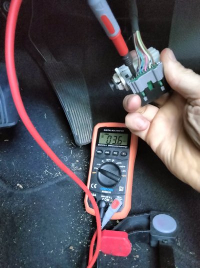
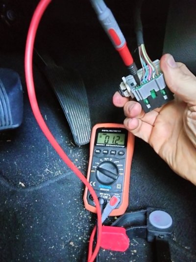
After replacing it, now I noticed that the damn brake lights are backwards. When my foot is off the brake, the tail lights illuminate or get brighter. When I press the brake pedal, they turn off. So, I put the previous switch in and now it's doing the same thing. What the hell Chrysler?
I searched AllData for any possible scenario, but I can't find anything that makes sense. Have any of you had this issue? I'm about to drive this damn Chrysler truck into a lake and claim insurance money based on an alien abduction where they stole my pickup. They wouldn't believe me because no one wants a 2012 Ram 1500 because it has a TIPM.
 

BossHogg

Senior Member
Joined
Feb 23, 2014
Posts
1,935
Reaction score
2,456
Location
Oakland Township, Michigan
Ram Year
2015
Engine
6.7L Cummins
Could it be as simple as an incorrect brake switch? Sounds like you have a normally closed versus normally open or vis-versa switch state. I don't know how the brake switch for your model year is wired.
 
OP
OP
ConorToot

ConorToot

Member
Joined
Jan 13, 2023
Posts
52
Reaction score
21
Location
Houston, Texas
Ram Year
2012
Engine
4.7L
I wish it were that easy. I put the one I was replacing back in and it was backwards too. I rang out both with my multi-meter and they are as the schematic indicates: Pins 1&2 normally closed, Pins 3&4 normally open, Pins 5&6 normally open. Then I pressed the plunger in and each activated opposite as they should. Electrical is normally my forte as I was trained and worked in Avionics when in the Navy. I've worked in the vehicle electronics field for twenty five years since. That's what's baffling to me with this issue. I've seen things not work, but I've never seen them reverse like this. I'm guessing that there is some cockamamie idiot engineering that decided to put some signal as a DC offset through one of the needless of the three stop lamp switch connections that has now gone missing. Because everything with the TIPM sucks, I'm going to assume the answer will be that I need a new TIPM that I can no longer buy because they don't make them anymore or something of that nature. And, I'm not spending anything more than $100 on this crappy truck that breaks faster than I can fix it. If anything, I'll build a workaround for the TIPM. I already had to do this for the fuel pump when it quit working, but that fix was really easy.
Below is what I confirmed with the two switches:
1702122886605.png
 
Last edited:

crash68

ACME product engineer
Staff member
Administrator
Supporting Member
Joined
Mar 20, 2016
Posts
10,791
Reaction score
16,932
Ram Year
2015
Engine
3.0 EcoDiesel
When my foot is off the brake, the tail lights illuminate or get brighter. When I press the brake pedal, they turn off.
almost sounds like a bad ground or something wrong with the bulbs
 
OP
OP
ConorToot

ConorToot

Member
Joined
Jan 13, 2023
Posts
52
Reaction score
21
Location
Houston, Texas
Ram Year
2012
Engine
4.7L
1702126249036.png

I think the answer can be found here. However, no where does it indicate any reading that I might find with a multi-meter. That's where I stop. There isn't one voltage, resistance, or measurement that can be used to really tell what's happening. That's why I hate most products that have schematics or wiring diagrams. Sure, I can ring out the line from point A to point B and tell if it's open, shorted, or disconnected. What I can't tell is what is supposed to be happening when it works correctly to compare it to what I'm reading on my end. So, mine always looks like it's operating perfectly other than the result - opposite brake lights.
 
OP
OP
ConorToot

ConorToot

Member
Joined
Jan 13, 2023
Posts
52
Reaction score
21
Location
Houston, Texas
Ram Year
2012
Engine
4.7L
almost sounds like a bad ground or something wrong with the bulbs
It would be the wrong bulbs except I didn't do anything to the bulbs and they were working for some time now. Possibly a bad ground. After staying up all night and reading everything I can on AllData, it might be the B+ signal that comes from the TIPM. They seem really proud for having fused something directly on the TIPM board rather than by adding a replaceable fuse. That worries the hell out of me. If the fuse on the TIPM blew, I have oodles of experience at component level diagnostics and I'll simply put a damn jumper over it instead of replacing it. Nothing should ever be fused on a board - NOTHING. The reason they put fuses on anything is as a designed fail point. So, that designed fail point should be replaceable and not on a board. That's these big, rich corporations designing reasons for you and I do purchase another when the one we have suddenly breaks for no discernable reason. I hate that and it makes me lose trust in anything Chrysler does. That, and the fact that they actually releasd the Chrysler K-Car and thought it was a good idea. Evidence of stupidity - Stupidity proven - K-Car.
 

RamDiver

Senior Member
Joined
Jan 23, 2022
Posts
2,138
Reaction score
3,521
Location
Marlborough, Ontario, Canada
Ram Year
2021
Engine
Hemi 5.7
Why would you choose to bypass a fuse?

I can appreciate you might not be satisfied with the location, then relocate the fuse.

Fuses aren't used to promote intentional failures but as a current limitation mechanism to prevent excessive current damage in components and conductors.

If you have experience in component level troubleshooting, this concept should be pretty obvious.

.
 
OP
OP
ConorToot

ConorToot

Member
Joined
Jan 13, 2023
Posts
52
Reaction score
21
Location
Houston, Texas
Ram Year
2012
Engine
4.7L
Why would you choose to bypass a fuse?

I can appreciate you might not be satisfied with the location, then relocate the fuse.

Fuses aren't used to promote intentional failures but as a current limitation mechanism to prevent excessive current damage in components and conductors.

If you have experience in component level troubleshooting, this concept should be pretty obvious.

.
You would think it would be obvious, but without knowing some readings when it works, it's very difficult to tell what is wrong when it doesn't work. You bypass a fuse that is mounted on a board so you can install a replaceable fuse off of the board. That way, you don't have to take the entire fuse box apart to get to the board if a fault causes the fuse to burn. You can then simply change the fuse. This is why fuses should not be soldered in at the component level.
So, I took the attached pictures of what I got when testing each wire with the switch activated (pushed in) and deactivated (extended). Maybe someone has seen something similar and can point me in the right direction. In the meantime, I'll be reviewing the wiring diagram to see if I can determine where the signals are different than what is expected. (That's the part that should be obvious and might be once I look at what I got and compare it to what the wiring diagram is showing.)
 

Attachments

  • IMG20231209082003.jpg
    IMG20231209082003.jpg
    113.7 KB · Views: 5
  • IMG20231209082008.jpg
    IMG20231209082008.jpg
    130.1 KB · Views: 5
  • IMG20231209082040.jpg
    IMG20231209082040.jpg
    123.2 KB · Views: 5
  • IMG20231209082046.jpg
    IMG20231209082046.jpg
    129.6 KB · Views: 4
  • IMG20231209082107.jpg
    IMG20231209082107.jpg
    136.3 KB · Views: 3
  • IMG20231209082123.jpg
    IMG20231209082123.jpg
    134 KB · Views: 3
  • IMG20231209082137.jpg
    IMG20231209082137.jpg
    122 KB · Views: 3
  • IMG20231209082140.jpg
    IMG20231209082140.jpg
    126.9 KB · Views: 3
  • IMG20231209082434.jpg
    IMG20231209082434.jpg
    113.1 KB · Views: 3
  • IMG20231209082439.jpg
    IMG20231209082439.jpg
    116.4 KB · Views: 3
  • IMG20231209082454.jpg
    IMG20231209082454.jpg
    120.9 KB · Views: 2
  • IMG20231209082457.jpg
    IMG20231209082457.jpg
    132.7 KB · Views: 4

jawzs2

Senior Member
Military
Joined
Mar 24, 2014
Posts
1,871
Reaction score
2,301
Location
South Jersey
Ram Year
2010, 2014
Engine
1500, 3500
So, I took the attached pictures of what I got when testing each wire with the switch activated (pushed in) and deactivated (extended)

If I'm reading this correctly, or maybe I'm misunderstanding what you are saying, I think you have this backwards The brake lamps should be off, (deactivated), with the plunger fully depressed - they should come on when the plunger is extended, (activated).

Here's out of my 2010 shop manual, maybe it'll help

The brake lamp switch controls three independent circuits. These circuits are described as follows:
  1. Brake Lamp Switch Circuit - A normally open brake lamp switch circuit receives a battery voltage input, and supplies this battery voltage to the Center High Mounted Stop Lamp (CHMSL) and the Totally Integrated Power Module (TIPM) on a brake lamp switch output circuit only when the brake pedal is depressed (brake lamp switch plunger released).
  2. Brake Lamp Switch Signal Circuit - A normally closed brake lamp switch signal circuit receives a direct path to ground, and supplies this ground input to the Powertrain Control Module (PCM) on a brake signal 1 circuit only when the brake pedal is released (brake lamp switch plunger is depressed).
  3. Speed Control Circuit - A normally closed speed control circuit receives a battery voltage input from the Totally Integrated Power Module (TIPM) on an ignition run/start control output circuit, and supplies this battery voltage to the PCM on a brake signal 2 circuit only when the brake pedal is released (brake lamp switch plunger is depressed).
 

LeeD

Senior Member
Supporting Member
Joined
May 14, 2020
Posts
192
Reaction score
177
Location
Humble, TX United States
Ram Year
2018
Engine
5.7 Hemi
This probably won’t be any help for you but just in case it is I thought I would post it.
My daughter had a 2001 VW Golf and we went through 4 different versions of brake switches until VW finally got it right. The brake switch had a very specific installation procedure. The switch came preset in a position for installation. If you activated the switch before installation it wouldn’t work once installed. Ask me how I know . Once I learned the procedure then the brake switch would work correctly. At least for a while.
I have no idea if this could be any help for you. Good luck.
 
OP
OP
ConorToot

ConorToot

Member
Joined
Jan 13, 2023
Posts
52
Reaction score
21
Location
Houston, Texas
Ram Year
2012
Engine
4.7L
View attachment 533095
You would think it would be obvious, but without knowing some readings when it works, it's very difficult to tell what is wrong when it doesn't work. You bypass a fuse that is mounted on a board so you can install a replaceable fuse off of the board. That way, you don't have to take the entire fuse box apart to get to the board if a fault causes the fuse to burn. You can then simply change the fuse. This is why fuses should not be soldered in at the component level.
So, I took the attached pictures of what I got when testing each wire with the switch activated (pushed in) and deactivated (extended). Maybe someone has seen something similar and can point me in the right direction. In the meantime, I'll be reviewing the wiring diagram to see if I can determine where the signals are different than what is expected. (That's the part that should be obvious and might be once I look at what I got and compare it to what the wiring diagram is showing.)
Okay, it looks like I might have it fixed. I've never done anything with any pin on the connectors of my truck, but after looking at the wiring diagram, then comparing it to the continuity test I did on all three switches, pins 5&6 were normally closed with pins 1&2 and 3&4 normally open. The chart shows that 1&2 should be normally closed. When I did the continuity test, I guessed that the pins closest to the plunger were 1&2 since they don't have them marked. When I looked at the connector, they are marked and I was measuring 5&6 as normally closed. Don't ask me what possibly could have changed because up until 24 hours ago, they were always working correctly. This truck has passed state inspections and I work with public transit police officers and drivers. Someone would have said something because they always tell me when my tires look low, if I didn't signal a turn, or if I rolled through a stop sign. They most assuredly would have noticed brake lights that worked opposite of normal standard brake lights.
For anyone who experiences opposite brake lights, below is how I re-pinned the connector:
Pin Wiring Diagram Color My Pin (Colors on my truck)
1: Light Green / Red 6: (Light Green / Red)
2: White 5: (White)
3: Pink 4: (Pink)
4: Light Blue / Orange 3: (Light Blue / Green)
5: Black / Tan 2: (Black / Tan)
6: Dark Green / White 1: (Dark Green / Orange)
 
OP
OP
ConorToot

ConorToot

Member
Joined
Jan 13, 2023
Posts
52
Reaction score
21
Location
Houston, Texas
Ram Year
2012
Engine
4.7L
View attachment 533095

Okay, it looks like I might have it fixed. I've never done anything with any pin on the connectors of my truck, but after looking at the wiring diagram, then comparing it to the continuity test I did on all three switches, pins 5&6 were normally closed with pins 1&2 and 3&4 normally open. The chart shows that 1&2 should be normally closed. When I did the continuity test, I guessed that the pins closest to the plunger were 1&2 since they don't have them marked. When I looked at the connector, they are marked and I was measuring 5&6 as normally closed. Don't ask me what possibly could have changed because up until 24 hours ago, they were always working correctly. This truck has passed state inspections and I work with public transit police officers and drivers. Someone would have said something because they always tell me when my tires look low, if I didn't signal a turn, or if I rolled through a stop sign. They most assuredly would have noticed brake lights that worked opposite of normal standard brake lights.
For anyone who experiences opposite brake lights, below is how I re-pinned the connector:
Pin Wiring Diagram Color My Pin (Colors on my truck)
1: Light Green / Red 6: (Light Green / Red)
2: White 5: (White)
3: Pink 4: (Pink)
4: Light Blue / Orange 3: (Light Blue / Green)
5: Black / Tan 2: (Black / Tan)
6: Dark Green / White 1: (Dark Green / Orange)
IMG20231209110349.jpg
You can see that the pinning is exactly opposite of the previous pictures where I was checking the signals on each (below). For whatever reason, my truck wants these wires to be flipped from the standard. I know they worked less than a week ago because I have swing out tool kits and was in the back with the engine running at night and I needed the cargo light on because the lights are on but fairly dim when it's just the running lights, but very bright when the brake is pressed.
Below is the way it was pinned hours ago when it was working in opposite patterns.
IMG20231209082137.jpg
If it melts down or something happens, I'll respond again to this post. For now, I'm considering the issue of opposite lights -=> SOLVED <=-
 

Latest posts

Forum statistics

Threads
195,652
Posts
2,872,937
Members
156,490
Latest member
OasisNinjaBat
Top