PSC1 installation help

Disclaimer: Links on this page pointing to Amazon, eBay and other sites may include affiliate code. If you click them and make a purchase, we may earn a small commission.

Redtruck-VA

Senior Member
Joined
Jun 29, 2010
Posts
5,864
Reaction score
984
Location
Virginia
Ram Year
2003 & 1989 D250 RWD
Engine
Hemi-5.7, 5.9 12v & 24v diesel
Hey Guys, I'm ready to install the PSC1 and quickly found I don't have any instruction on how to install the unit on my truck. My laptop had a melt down and couldn't get most of my files off of it, so I'm starting from scatch. Did the usual searches and came up pretty much empty handed. Moe's was said the have an installation guide, but it is nolonger there. Split Second doesn't have anything I could find. I did find some information from the DT site. And will be following what they did in locating the unit on the passenger kick panel, running the wires up through the firewall to the PCM. Found a note saying to get the rpm input from the yellow wire with the black strip from number 8 injector. But that is it. Anyone have a link to a DIY, or knowledge on how to connect the wiring?
Any help is appreciated.
Thanks,
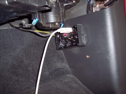
1001939p.jpg
 
Last edited:
OP
OP
Redtruck-VA

Redtruck-VA

Senior Member
Joined
Jun 29, 2010
Posts
5,864
Reaction score
984
Location
Virginia
Ram Year
2003 & 1989 D250 RWD
Engine
Hemi-5.7, 5.9 12v & 24v diesel
This is what i have come up with:
PSC1 - Truck
Red = 12v switched with ignition DG/OR (19/C2)
Black = Grd
Violet = Cut DG/RD (MAF) wire going to PCM (23/C2)
Yel & Grn (2)wires = Cut DG/RD (MAF) coming from MAF (23/C2)
Yel/Blk = GY/LB #8 Inj (4/C1) Tach
Yel/Grn = Not Used, this is a Yel wire with Grn strip
 
Last edited:
OP
OP
Redtruck-VA

Redtruck-VA

Senior Member
Joined
Jun 29, 2010
Posts
5,864
Reaction score
984
Location
Virginia
Ram Year
2003 & 1989 D250 RWD
Engine
Hemi-5.7, 5.9 12v & 24v diesel
Haha, we will see when I plug this in and try to fire the old girl up.... Actually pretty simple just got to locate the right wires..
 

03MopaRamman

RAM SPORT / 18 SRT
Joined
Jul 3, 2010
Posts
3,580
Reaction score
186
Location
Southern Alberta
Ram Year
2019 (2003 Forgottens SOLD and 2014 SOLD)
Engine
Hemi 5.7 (392 Hemi) 86 Ford .308 HO Roller
Greg I still got all the files including what you sent me. A sample as follows.

>>>>>This is how to wire it up on an 03'<<<<<(Info found on another Forum/Thanks to that Author Dude)

Red wire t-taps to (C1P29) Red w/ White Stripe
Black wire t-taps to (C2P27) Black w/ Light Brown Stripe MAP Sensor Ground (Middle wire of MAP Sensor)
Cut MAP Sensor Signal Wire about 6" from PCM. This wire is Green w/ Red Stripe going to C2
Violet wire splices to (C2P23 Green w/ Red Stripe) cut end of MAP wire on the PCM side
Yellow wire and Green wire go together and splice into cut end of MAP wire on the MAP Sensor side Green w/ Red Stripe wire
Yellow w/ Black Stripe wire t-taps to tach signal off #8 Injector. The wire closest to the red clip
Yellow w/Green Stripe wire is not used (not in diagram but is on the PSC1-003)
Click on pics below to enlarge.
Pic of the 03' MAP Sensor
C1 on an 03'
C2 on an 03'
PH

NOTE: Oh and the Black wire from the PSC going to the Map Sensor is Black w/blue stripe. Not Black w/Light Brown as indicated earlier.

Greg, I can email them to you if you like?
 
Last edited:
OP
OP
Redtruck-VA

Redtruck-VA

Senior Member
Joined
Jun 29, 2010
Posts
5,864
Reaction score
984
Location
Virginia
Ram Year
2003 & 1989 D250 RWD
Engine
Hemi-5.7, 5.9 12v & 24v diesel
Greg I still got all the files including what you sent me. A sample as follows.

>>>>>This is how to wire it up on an 03'<<<<<(Info found on another Forum/Thanks to that Author Dude)

Red wire t-taps to (C1P29) Red w/ White Stripe
Black wire t-taps to (C2P27) Black w/ Light Brown Stripe MAP Sensor Ground (Middle wire of MAP Sensor)
Cut MAP Sensor Signal Wire about 6" from PCM. This wire is Green w/ Red Stripe going to C2
Violet wire splices to (C2P23 Green w/ Red Stripe) cut end of MAP wire on the PCM side
Yellow wire and Green wire go together and splice into cut end of MAP wire on the MAP Sensor side Green w/ Red Stripe wire
Yellow w/ Black Stripe wire t-taps to tach signal off #8 Injector. The wire closest to the red clip
Yellow w/Green Stripe wire is not used (not in diagram but is on the PSC1-003)
Click on pics below to enlarge.
Pic of the 03' MAP Sensor
C1 on an 03'
C2 on an 03'
PH

NOTE: Oh and the Black wire from the PSC going to the Map Sensor is Black w/blue stripe. Not Black w/Light Brown as indicated earlier.

Greg, I can email them to you if you like?

Danny, this is good.
Thanks, I really appreciate the info.
 
Last edited:
OP
OP
Redtruck-VA

Redtruck-VA

Senior Member
Joined
Jun 29, 2010
Posts
5,864
Reaction score
984
Location
Virginia
Ram Year
2003 & 1989 D250 RWD
Engine
Hemi-5.7, 5.9 12v & 24v diesel
Well, got a problem. Fired her up and on the dash I have lighting bolts on the TB icon. She's running really fat. Wired it so I could simple plug it back together to bypass the PSC1. Basically everything stays wired up but the MAP sensor. Plugged the Map connections back together and all is well. Went back over all the connections and retested the lot and the only thing I found was that the MAP sensor ground BLK/LB is not true ground. Everything appears as it should, but something really is not right. I haven't checked the PSC1 file yet basically because I don't know how. Will figure out how to use the software tonight.

Red wire t-taps to (C1P29) Red w/ White Stripe
Black wire t-taps to (C2P27) Black w/ Light Brown Stripe MAP Sensor Ground (Middle wire of MAP Sensor)
Note: This is Blue not Brown. Should read:
Black wire t-taps to (C2P27) Black w/ Light Blue Stripe MAP Sensor Ground (Middle wire of MAP Sensor)Cut MAP Sensor Signal Wire about 6" from PCM. This wire is Green w/ Red Stripe going to C2
Violet wire splices to (C2P23 Green w/ Red Stripe) cut end of MAP wire on the PCM side
Yellow wire and Green wire go together and splice into cut end of MAP wire on the MAP Sensor side Green w/ Red Stripe wire
Yellow w/ Black Stripe wire t-taps to tach signal off #8 Injector. The wire closest to the red clip
Yellow w/Green Stripe wire is not used (not in diagram but is on the PSC1-003)
 
Last edited:
OP
OP
Redtruck-VA

Redtruck-VA

Senior Member
Joined
Jun 29, 2010
Posts
5,864
Reaction score
984
Location
Virginia
Ram Year
2003 & 1989 D250 RWD
Engine
Hemi-5.7, 5.9 12v & 24v diesel
It's tore all a part again from being checked. Can't find any reason it isn't working. Studied up on how to read and adjust the files. Simple enough.. But guess what, my new laptop "Windows 7" won't load the drivers for the serial/USB cable. So my Laptop won't connect. This really ****** me off, but fortunately I have the patience of a ******* monk! Well the good news today is the guy who lives in the brown truck swung by and dropped off my dual window switch. Oh did i say anything about getting a new droid, another week or so and i should have it figured out enough to make a call. Side note, checked my Amex account and saw the wife wasn't killing me with debt. Started to actually worry a little and sure enough gat the email from her (she's in the PI) asking if I had seen her card.. meaning she has lost her card... perfect!, just perfect.... ugggh
 

hemifever

Senior Member
Preferred Vendor
Joined
Aug 10, 2010
Posts
377
Reaction score
107
Location
Apex, NC
Ram Year
2003
Engine
5.7
I believe 10's in the r4 software are "no" change in the cells. If you hooked up to any of the o2 sensor leads in the pcm, unhook those as sometimes it will skew the voltage to the o2 and cause it to run rich.

And just to confirm some stuff you probably mentioned earlier :

In C2
The map sensor wire to cut in to : Dk Grn/Red tracer
Fused power : Red/White tracer
Crank : Gry/Black tracer
 
Last edited:
OP
OP
Redtruck-VA

Redtruck-VA

Senior Member
Joined
Jun 29, 2010
Posts
5,864
Reaction score
984
Location
Virginia
Ram Year
2003 & 1989 D250 RWD
Engine
Hemi-5.7, 5.9 12v & 24v diesel
I believe 10's in the r4 software are "no" change in the cells. If you hooked up to any of the o2 sensor leads in the pcm, unhook those as sometimes it will skew the voltage to the o2 and cause it to run rich.

And just to confirm some stuff you probably mentioned earlier :

In C2
The map sensor wire to cut in to : Dk Grn/Red tracer
Fused power : Red/White tracer
Crank : Gry/Black tracer

In C2
The map sensor wire to cut in to : Dk Grn/Red tracer (correct)
Fused power : Red/White tracer (correct)
Crank : Gry/Black tracer (is this for rpm?, I'm connected to GY/LB #8 injector)
I'm not connected to the O2 sensor.
Would I do better wiring to GY/BK (crank sensor) than connected to #8 injector?

Sean, Yes from what I have read "10" are "no change" I set up a map with all 10's to load, thinking the map that the ECU now has is something other than 10's. Unfortunately my laptop won't connect. But I'm also thinking that something still isn't right because of the lighting bolts (TB) being shown on the dash.
 
Last edited:
OP
OP
Redtruck-VA

Redtruck-VA

Senior Member
Joined
Jun 29, 2010
Posts
5,864
Reaction score
984
Location
Virginia
Ram Year
2003 & 1989 D250 RWD
Engine
Hemi-5.7, 5.9 12v & 24v diesel
Ok, here where I am at;
Red wire t-taps to (C1P29) Red w/ White Stripe
*Black wire connected to chasis ground
Violet wire splices to (C2P23 Green w/ Red Stripe) cut end of MAP wire on the PCM side
Yellow wire and Green wire go together and splice into cut end of MAP wire on the MAP Sensor side Green w/ Red Stripe wire
*Yellow w/ Black Stripe wire t-taps to tach signal off of Crank Sensor GY/BK (C2)
Yellow w/Green Stripe wire is not used (not in diagram but is on the PSC1-003)
* notes changes from last test.
Got same indication TB icon lighting bolt.
Re-Connect MAP G/RD wire straght back to PCM and no TB icon lighting bolt.

This is simply stuff, any ideas?

Edit: Conclusion, bad PSC1-003.
Re tested everything and the PSC1 is not working. The truck runs the same with the PSC1 as it does with the MAP disconnected. This also explains why my laptop won't connect to the PSC1. Physically checked every connection and removed plugs that could have been the problem. The PCM has enough wire attached that it can be pulled away from the firewall with plenty of room to do an easy job of it. I have a CAI and removed it to get into the corner. I hope, me having a problem doesn't deter anyone from using the PSC1 as I think it is part of the solution needed in taming the 03 and the installation is not difficult. Now that I have learned the layout and know how to read the plugs it's a simple install.

The PSC1 was bought used and I don't have it's history. Maybe the seller will chime in.

Update: Removed the PSC1, which returned everything back to normal. Ordered a new PSC1-003 from Duane. Still have the headers, window switch and linelok to install. And the new PSC1 when it arrives.
 
Last edited:

hemifever

Senior Member
Preferred Vendor
Joined
Aug 10, 2010
Posts
377
Reaction score
107
Location
Apex, NC
Ram Year
2003
Engine
5.7
Hopefully that's the issue. It's really not rocket science to hook it up lol. I did try their o2 specific unit some time back and every time it even touched the o2 signal wire it would jack voltage up to 5. almost sounds like it was doing that to the map
 
OP
OP
Redtruck-VA

Redtruck-VA

Senior Member
Joined
Jun 29, 2010
Posts
5,864
Reaction score
984
Location
Virginia
Ram Year
2003 & 1989 D250 RWD
Engine
Hemi-5.7, 5.9 12v & 24v diesel
Sean, I don't know how to bench test the PSC1, but the truck when connected to the PSC1 ran the same as if the MAP signal wire GRN/Rd was cut. When the GRN/RD wire was re-connected it would go back to normal. Plus the laptop would not communicate with the PSC1. I'll know for sure when the new PSC1 is installed. Looking at the PSC1 unit it looks good, no apparent physical damage, no burnt smell, wires appear to never been connected, box in good condition and complete with disc's and instructions look clean. Basically, my impression is that the unit has never been installed, but will compare the wire lengths with the new unit.
 
OP
OP
Redtruck-VA

Redtruck-VA

Senior Member
Joined
Jun 29, 2010
Posts
5,864
Reaction score
984
Location
Virginia
Ram Year
2003 & 1989 D250 RWD
Engine
Hemi-5.7, 5.9 12v & 24v diesel
Ok, while I am waiting for the new PSC1 to arrive I would like to clarify some information on the Tach input.
The question is: Do I connect to the Yellow w/ Black Stripe wire that t-taps to tach signal off #8 Injector ?
Or do I connect to the Gray w/ Black stripe wire that t-tap to the Crank Sensor?
It is not a problem doing either one.
Inputs are appreciated
 

rocket

Licensed Dynacologist
Joined
Jun 26, 2010
Posts
18,075
Reaction score
3,919
Location
connecticut
Ram Year
was 2006
Engine
was a HEMI 5.7
I'm about as confused as a jew looking for a quarter in the corner of a synagogue
 
OP
OP
Redtruck-VA

Redtruck-VA

Senior Member
Joined
Jun 29, 2010
Posts
5,864
Reaction score
984
Location
Virginia
Ram Year
2003 & 1989 D250 RWD
Engine
Hemi-5.7, 5.9 12v & 24v diesel
I'm about as confused as a jew looking for a quarter in the corner of a synagogue

Bill, sorry to confuse, but this is information needed for install of the PSC1, Tach lite, window switch or anything that needs a rpm trigger. Just trying to sort out if either source works and if one works better than the other.
If you have a specific question, by all means throw it out and I'll attempt to answer or hopefully someone will.
 

rocket

Licensed Dynacologist
Joined
Jun 26, 2010
Posts
18,075
Reaction score
3,919
Location
connecticut
Ram Year
was 2006
Engine
was a HEMI 5.7
Yeah, No worries. Just what does a pcs 1 do anyway? That would prolly clear up the fog.
 
OP
OP
Redtruck-VA

Redtruck-VA

Senior Member
Joined
Jun 29, 2010
Posts
5,864
Reaction score
984
Location
Virginia
Ram Year
2003 & 1989 D250 RWD
Engine
Hemi-5.7, 5.9 12v & 24v diesel
Well Guys and Girls, the new PSC1 should arrives tomorrow and I'll get home Thursday so if you can help me with deciding which to try first, it would be appreciated.

The question is: Do I connect to the Yellow w/ Black Stripe wire that t-taps to tach signal off #8 Injector ?
Or do I connect to the Gray w/ Black stripe wire that t-tap to the Crank Sensor?

Thanks,
 

03MopaRamman

RAM SPORT / 18 SRT
Joined
Jul 3, 2010
Posts
3,580
Reaction score
186
Location
Southern Alberta
Ram Year
2019 (2003 Forgottens SOLD and 2014 SOLD)
Engine
Hemi 5.7 (392 Hemi) 86 Ford .308 HO Roller
Bill I'm still sittin in the weeds too! Greg the instructions talk about the Yellow w/ Black Stripe wire that t-taps to tach signal off #8 Injector, so try that. As for the other wire, "duh" I didn't think the 03 had a Crank sensor. Guess mine works as I never paid any attention. Keep feeding the Info man, this is getting interesting!

Did you still have a copy of the Tuning tutorial PDF. don't know how to attach it here!
 
Last edited:
Top