
itswiggs
Member
- Joined
- Jul 30, 2024
- Posts
- 37
- Reaction score
- 35
- Location
- texas
- Ram Year
- 2022
- Engine
- pentastar etorque
I saw all the different harnesses you can get from jhd, boost and ddp with jhd being the most budget friendly route and ddp being the most expensive but least invasive as far as dismantling the vehicle.
It got me thinking though because it seems these harnesses are utilizing diodes and or relays in some fashion. with tapping into the DRL driver on the bcm for each driver and passenger side you can effectively use the jhd harness and get the effect of boost or ddp (I.e. DRL dropout when signal is engaged) as long as you have everything enabled through alpha.
The power for the turn signal on the mirror is already present at the module. All that needs to be done is to introduce the constant hot from bcm for the drl. If drl dropout is enabled in alpha then this method will work.
I’m sure there are other ways to manipulate the wiring through a relay but unless you know how to do it the correct way it’d be some trial and error. I’ll post a link to a video from flyryde that actually shows how to wire switchbacks with a relay and capacitor.

 youtu.be
Edit/update: I followed the exact procedure from this flyryde video at the door module using the relay, capacitor and diode. Just wanted to say that it worked for me in that when the headlights are on (drl off and “parking light” on) the mirror turn signal turns completely off, on, off, on the same as the ddp harness. If you don’t want to spend the extra money, have a little want to and know how then this set up works just fine and pretty neat to learn something new. My lights on the mirror are only amber but if you have switchbacks it’ll work as well.
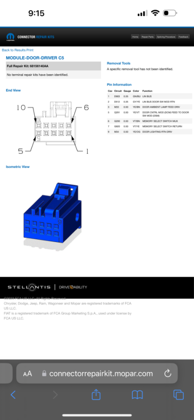
I watched ddp’s video of their harness install and utilized the back lit door handle circuit by tapping into the signal (hot) and return (ground). I will post a pic of the pin out for the blue connector. You will still need to wire it in correctly and use the diodes to prevent back feed. Will need the te receptacles as well to plug into the connector and enable through alpha.
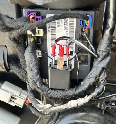
This is how I wired the relay initially before adding the capacitor and diode at the door module. You can see where I mounted it on the door module using the torx screw for the bottom tab of the module. I didn’t take pictures of the final but if anyone is curious I can help walk through it.
Here below is the original post explaining how I tapped into drl driver for the original project….
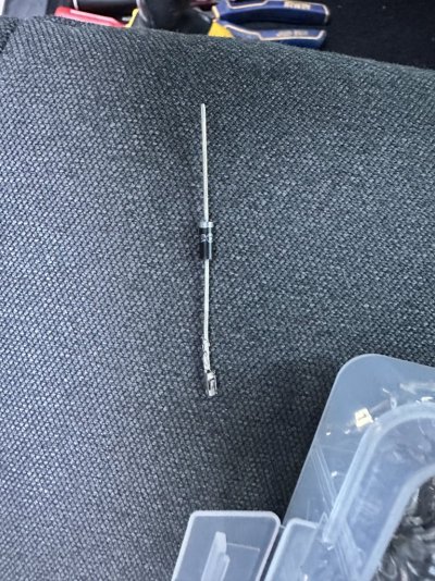
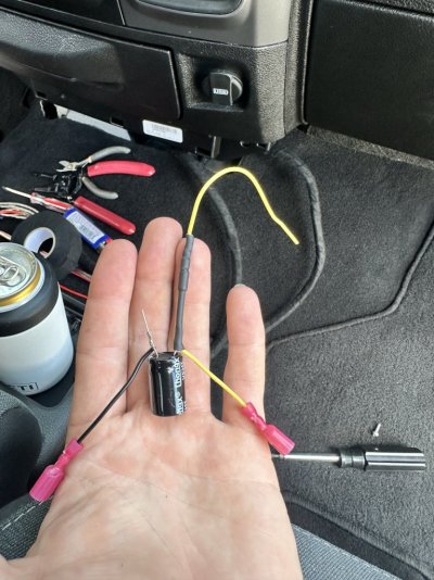
Ok so here is the set up I rigged up for the diodes at the door modules. I pulled the pin 9 wire from the black connector going to the mirror and crimped the same receptacle to the end of a diode so it will fit back into the connector and back into the module.
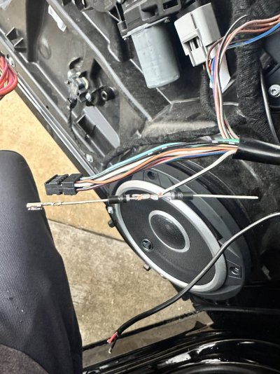
Then crimped another diode and the wire from pin 9 all together as you see in the pic. Notice how the wire to the mirror from pin 9 is between the diodes and the orientation to which the diodes are facing. Power needs to flow the right way and not back or else it won’t work the right way and will back feed causing unwanted issues.
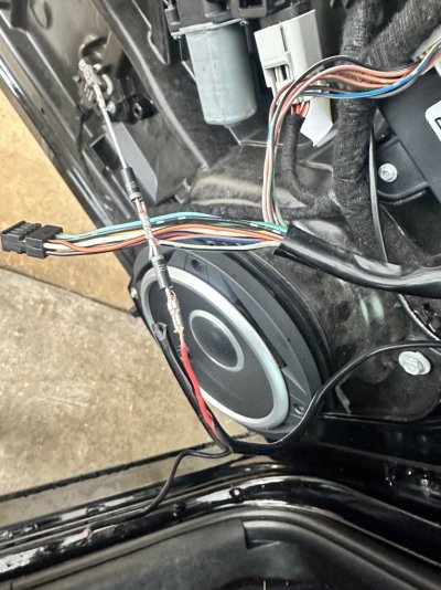
The power wire for the DRL from the bcm to the end of the 2nd diode gets crimped here. This wire you’ll run through the boot and all that fun stuff.
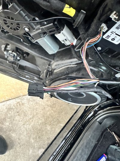
Insert the receptacle and diode configuration back into pin 9. use plenty of heat shrink in b/w everything to make sure nothing shorts.
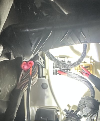
T-tap the drl driver at the bcm for each driver side and passenger side accordingly
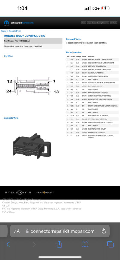
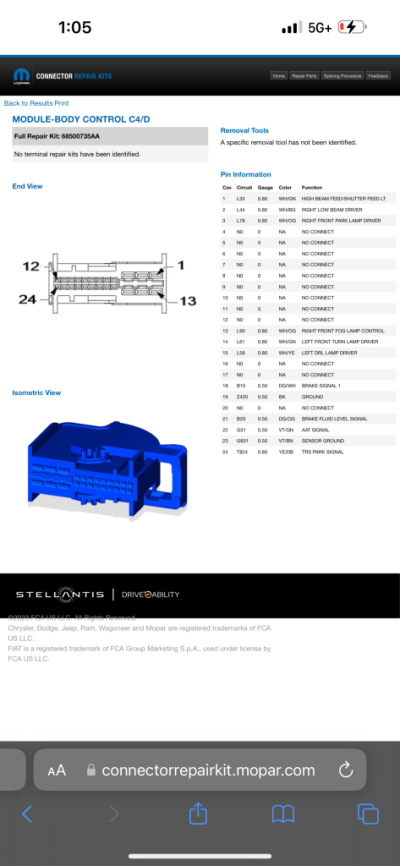
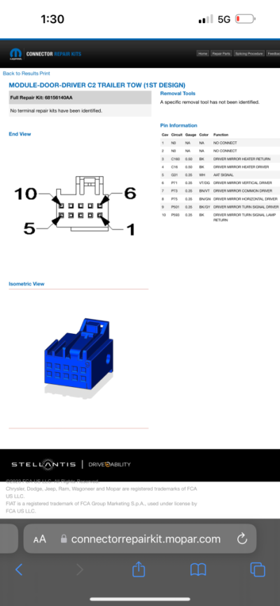
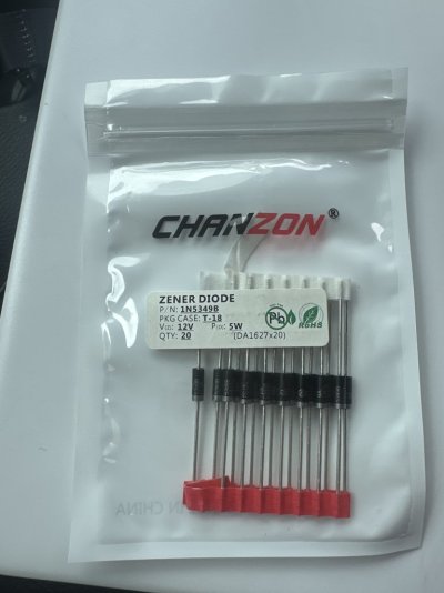
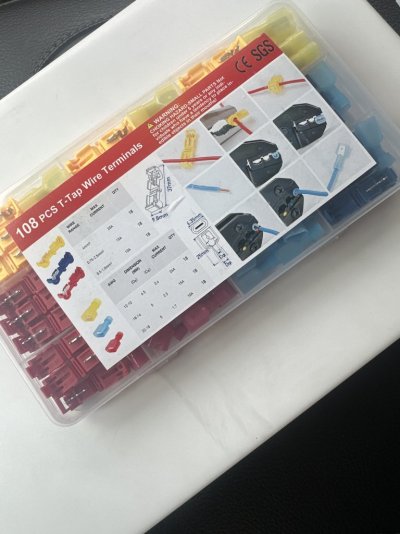
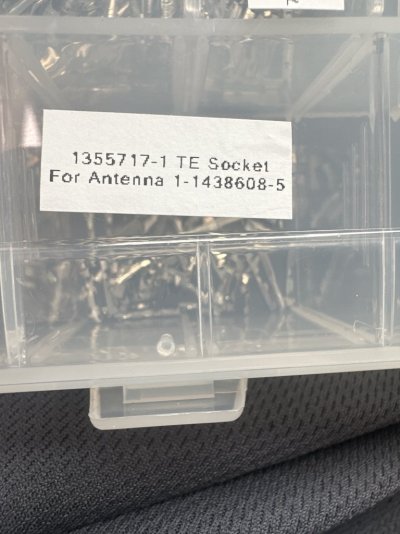
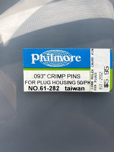
For the crimps I used the te socket for pin 9 in the door module connectors and everything else I used the philmore. Cut off the tab or receptacle part and just use the crimp itself.
The configuration done with the diodes i believe would work for the parking lights, however it would be done at the Bcm side. Not sure though maybe this part would need a relay
It got me thinking though because it seems these harnesses are utilizing diodes and or relays in some fashion. with tapping into the DRL driver on the bcm for each driver and passenger side you can effectively use the jhd harness and get the effect of boost or ddp (I.e. DRL dropout when signal is engaged) as long as you have everything enabled through alpha.
The power for the turn signal on the mirror is already present at the module. All that needs to be done is to introduce the constant hot from bcm for the drl. If drl dropout is enabled in alpha then this method will work.
I’m sure there are other ways to manipulate the wiring through a relay but unless you know how to do it the correct way it’d be some trial and error. I’ll post a link to a video from flyryde that actually shows how to wire switchbacks with a relay and capacitor.
EASIEST Way To Make a SWITCHBACK MODULE
This is my OG secret to making Switchback Modules, back before you could buy them.I put a product list together for you in Amazon:https://amzn.to/3v8a1O6Rela...
youtu.be
Edit/update: I followed the exact procedure from this flyryde video at the door module using the relay, capacitor and diode. Just wanted to say that it worked for me in that when the headlights are on (drl off and “parking light” on) the mirror turn signal turns completely off, on, off, on the same as the ddp harness. If you don’t want to spend the extra money, have a little want to and know how then this set up works just fine and pretty neat to learn something new. My lights on the mirror are only amber but if you have switchbacks it’ll work as well.
I watched ddp’s video of their harness install and utilized the back lit door handle circuit by tapping into the signal (hot) and return (ground). I will post a pic of the pin out for the blue connector. You will still need to wire it in correctly and use the diodes to prevent back feed. Will need the te receptacles as well to plug into the connector and enable through alpha.
This is how I wired the relay initially before adding the capacitor and diode at the door module. You can see where I mounted it on the door module using the torx screw for the bottom tab of the module. I didn’t take pictures of the final but if anyone is curious I can help walk through it.
Here below is the original post explaining how I tapped into drl driver for the original project….
Ok so here is the set up I rigged up for the diodes at the door modules. I pulled the pin 9 wire from the black connector going to the mirror and crimped the same receptacle to the end of a diode so it will fit back into the connector and back into the module.
Then crimped another diode and the wire from pin 9 all together as you see in the pic. Notice how the wire to the mirror from pin 9 is between the diodes and the orientation to which the diodes are facing. Power needs to flow the right way and not back or else it won’t work the right way and will back feed causing unwanted issues.
The power wire for the DRL from the bcm to the end of the 2nd diode gets crimped here. This wire you’ll run through the boot and all that fun stuff.
Insert the receptacle and diode configuration back into pin 9. use plenty of heat shrink in b/w everything to make sure nothing shorts.
T-tap the drl driver at the bcm for each driver side and passenger side accordingly
For the crimps I used the te socket for pin 9 in the door module connectors and everything else I used the philmore. Cut off the tab or receptacle part and just use the crimp itself.
The configuration done with the diodes i believe would work for the parking lights, however it would be done at the Bcm side. Not sure though maybe this part would need a relay
Last edited: