
robval1987
Junior Member
- Joined
- Jul 25, 2015
- Posts
- 15
- Reaction score
- 24
- Location
- Lawton, OK
- Ram Year
- 2013 Ram 1500 Longhorn Laramie
- Engine
- Hemi 5.7
This post is made from several other posts that I found and some wire working and custom wiring to make work. So if your not good with wiring get some help from someone.
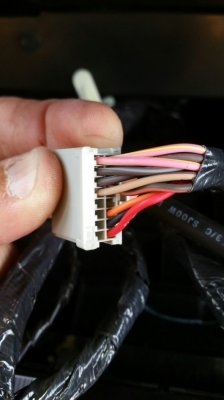
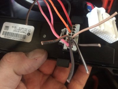
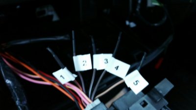
Well I took what you posted and the info in the private message and it worked out. The switch that I ordered was Mopar part # 68231816AD, that is the number required for trucks that have traction control, tow haul, exhaust brake and rear parking/backup sensors and 1-5 auxiliary switches. You have to remove your trailer brake control and add it into your switch panel (pop out of old one and snap it into the new one). I then removed the black tape on the switch harness freeing up more wire to work with. I then cut five wires,
#1 brown w/orange tracer,*
#2 brown w/purple tracer
(these 2 switches do not require the key to be in the ignition to work, they work all the time so remember to turn them off before leaving your truck),*
#3 brown w/white tracer,*
#4 brown w/light blue tracer,*
#5 tan w/brown tracer
(these 3 switches work with the ignition on, or truck running).*
*(THESE FIVE WIRES ARE FOR YOUR GROUND TO YOUR RELAYS ONLY, DO NOT ADD ANY POWER TO THESE WIRES! THEY ONLY COMPLETE A GROUND EFFECT.)
I tagged my wires with numbers corresponding to the number on the switch. I applied heat shrink to all my wires and screwed the switch back into place. I then closed up my center counsel and will build my relay block and be back with photos of this.
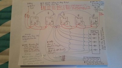
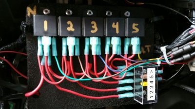
Well I finished the wiring on the Aux switch panel and it turned out great. I purchased these few items from my local O'Reillys Auto Parts store. 5 each 12 volt 30 amp 4 prong relays ($ 6.00 each), 1 each 5 gang fuse box with side connectors ($12.00), Radio Shack for 2 packages of 6 amp diodes, 4 in each pack, you need 5 total ($3.95×2=$7.90), miscellaneous connectors and wire. Don't forget that aux switches 1&2 are hot all the time, and aux switches 3,4&5 are run with key in either acc/run position. I began by attaching all 5 relays together with double sided tape then attached them to my project board (5×8 piece of plastic). I then attached the fuse box. I then daisy chained a (12 gauge) wire to terminal #30 on each relay then out to the battery with a 30 amp fuse holder (fuse removed for safety reason for now) and connected it to the driver's side positive battery terminal. I then ran a 2nd wire (16 gauge) from the same post with a 10 amp fuse holder (again remove fuse for now) then to the relays and daisy chained it to relays 1&2 to terminal #86. Relay 3,4&5 daisy chained to terminal #86 and get spliced/wired (16 gauge) into the 12 volt supply from the cig/aux charger. I then wired in all 5 relays (14 gauge) wire from terminal #87 to the new fuse box. I then connected the wires from the switch panel to a diode (6 amp) to the appropriate relay and attached it to terminal #85 (which is the trigger for each relay). Place the two fuses in their fuse holders and check to ensure you have power at your new fuse box with a light probe or volt meter when the switch is activated. Then connect what ever accessories you want to use with your aux switches (remember not to overload your new fuse box) to the new fuse box (don't for get to istall a fuse). If fail to put in the diodes you will see that when you turn on any Aux switch all 5 leds will illuminate on the Aux switches (it will not activate the switch, only illuminate the button). You need to ensure you put the diode in line correctly or the switch won't work, remember diodes only allow current to flow one way, and even though we are using a negative trigger it can get slight voltage to illuminate the leds. Here are a few photos and a hand drawn illistration (it is in different colors to help with viewing) I wired mine mostly in red wire. Hope this helps.
Well I took what you posted and the info in the private message and it worked out. The switch that I ordered was Mopar part # 68231816AD, that is the number required for trucks that have traction control, tow haul, exhaust brake and rear parking/backup sensors and 1-5 auxiliary switches. You have to remove your trailer brake control and add it into your switch panel (pop out of old one and snap it into the new one). I then removed the black tape on the switch harness freeing up more wire to work with. I then cut five wires,
#1 brown w/orange tracer,*
#2 brown w/purple tracer
(these 2 switches do not require the key to be in the ignition to work, they work all the time so remember to turn them off before leaving your truck),*
#3 brown w/white tracer,*
#4 brown w/light blue tracer,*
#5 tan w/brown tracer
(these 3 switches work with the ignition on, or truck running).*
*(THESE FIVE WIRES ARE FOR YOUR GROUND TO YOUR RELAYS ONLY, DO NOT ADD ANY POWER TO THESE WIRES! THEY ONLY COMPLETE A GROUND EFFECT.)
I tagged my wires with numbers corresponding to the number on the switch. I applied heat shrink to all my wires and screwed the switch back into place. I then closed up my center counsel and will build my relay block and be back with photos of this.
Well I finished the wiring on the Aux switch panel and it turned out great. I purchased these few items from my local O'Reillys Auto Parts store. 5 each 12 volt 30 amp 4 prong relays ($ 6.00 each), 1 each 5 gang fuse box with side connectors ($12.00), Radio Shack for 2 packages of 6 amp diodes, 4 in each pack, you need 5 total ($3.95×2=$7.90), miscellaneous connectors and wire. Don't forget that aux switches 1&2 are hot all the time, and aux switches 3,4&5 are run with key in either acc/run position. I began by attaching all 5 relays together with double sided tape then attached them to my project board (5×8 piece of plastic). I then attached the fuse box. I then daisy chained a (12 gauge) wire to terminal #30 on each relay then out to the battery with a 30 amp fuse holder (fuse removed for safety reason for now) and connected it to the driver's side positive battery terminal. I then ran a 2nd wire (16 gauge) from the same post with a 10 amp fuse holder (again remove fuse for now) then to the relays and daisy chained it to relays 1&2 to terminal #86. Relay 3,4&5 daisy chained to terminal #86 and get spliced/wired (16 gauge) into the 12 volt supply from the cig/aux charger. I then wired in all 5 relays (14 gauge) wire from terminal #87 to the new fuse box. I then connected the wires from the switch panel to a diode (6 amp) to the appropriate relay and attached it to terminal #85 (which is the trigger for each relay). Place the two fuses in their fuse holders and check to ensure you have power at your new fuse box with a light probe or volt meter when the switch is activated. Then connect what ever accessories you want to use with your aux switches (remember not to overload your new fuse box) to the new fuse box (don't for get to istall a fuse). If fail to put in the diodes you will see that when you turn on any Aux switch all 5 leds will illuminate on the Aux switches (it will not activate the switch, only illuminate the button). You need to ensure you put the diode in line correctly or the switch won't work, remember diodes only allow current to flow one way, and even though we are using a negative trigger it can get slight voltage to illuminate the leds. Here are a few photos and a hand drawn illistration (it is in different colors to help with viewing) I wired mine mostly in red wire. Hope this helps.