
RamblinRod
Senior Member
- Joined
- Jan 2, 2016
- Posts
- 127
- Reaction score
- 42
- Location
- Crawford, CO
- Ram Year
- 2016 Ram 2500 CC LB 4x4
- Engine
- 6.7 Cummins
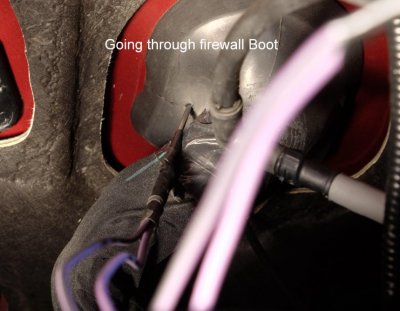
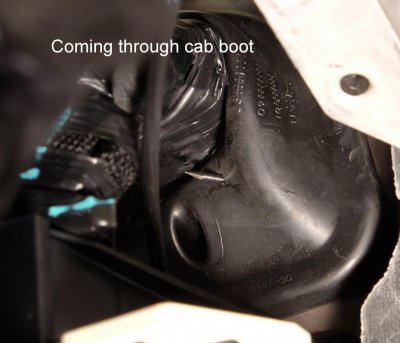
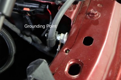
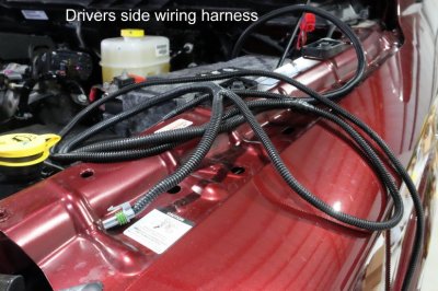
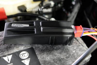
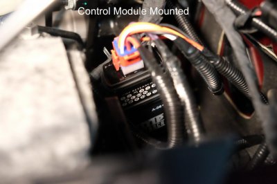
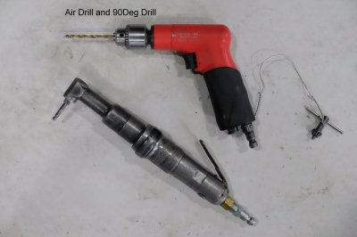
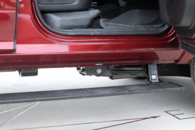
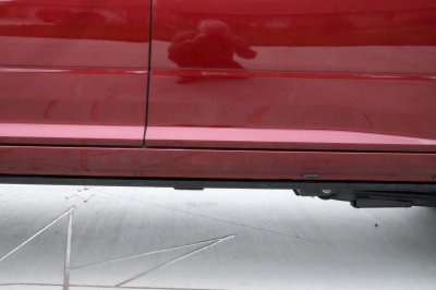
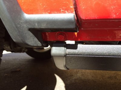
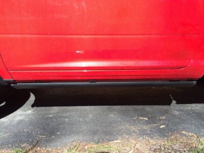
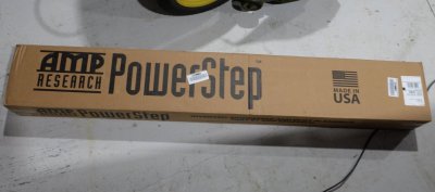
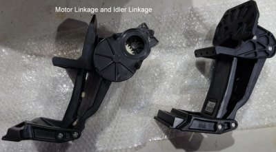
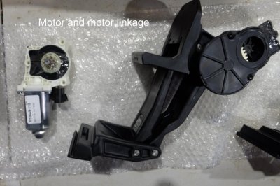
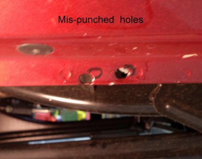
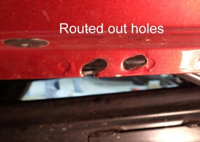
Just got these installed. Thought I would post some tips/info for others considering them. If you have a 2013 to 2016 without the new drivers side brace you want part #76138-A. That is the plug and play version. If you have the rear air suspension like I do, you need a tank relocate kit part #10-79102-01A. If you have a Mega Cab, the tank and compressor get relocated and its a different part #. The tank relocate is no big deal, two brackets that move the tank rearward 2" and up 1 1/2". Nothing gets disconnected. I paid $30 for it on Amazon. You can read the directions online. I will just cover some things I ran into. The linkage arms are attached with two bolts on mounting points on the inside of the rocker panel, two screws through punched holes in the pinch weld and two pop rivets at the top of the brackets. The directions say you may have to file some on the punched holes to line up with the screw holes in the linkage brackets. That was a major understatement. 5 of the 8 holes had to be enlarged. One set was badly mis-punched and I had to more than double the size of the holes. I was glad to have a die grinder with a burr to use. You have to run the two trigger wires through the firewall to connect to the OBD port. Directions said to cut a small hole in the rubber boot, lube up the wires and slide them through the other end of the boot into the cab. On my truck the inner boot where the wires exited was so wrapped up with tape I didn't want to mess with it. I put a needle point on a tig electrode, taped the wires to it and pushed it through both rubber boots. I cut Xs where it entered and exited to allow the wires to pass through. Worked like a charm. One of the last steps in the directions is measure and drill 9/16" holes through the pinch welds for the LED light wires. This can be one of the first things you do, put some primer on them and work on other things while it is drying. The control module mounts near the battery, the power lead is connected to the battery and the ground to the frame. There was a stud with a ground wire near the battery that the module ground wire fit on. I bought a 6mm 1.0 thread nut to secure it. One problem I read several times was people having their steps hang up on the pinch weld, especially the end caps, even have to disconnect the motors to get them back down. Some people have even ground some off the bottom edge of the pinch welds or bent them over with a hammer to get clearance. The directions have you mount the motors, then mount the steps and activate them. If they are hanging up they tell you to jump up and down on them to set the linages . I decided to mount the steps before mounting the motors. I did this after I had routed all the wiring harness, and had hooked up the LED lights. Without the motors installed I was able to move the steps and check the clearance. Initially both of mine were catching on the end caps but nowhere else. I jumped up and down four or five times at each linkage location and checked again. The steps were now 1/4 to 3/8" lower and totally clearing everything. Then I mounted the motors. I think that sequence makes much more sense. The last step is drilling 3/16" holes and installing pop rivets in the top of the idler arm brackets. Not even sure why they are needed. The idler linkages were not a big problem, I was able to get at them with a small air drill, but the motor linkages each had a hole that required a 90 deg drill to get too. On the passenger side I could not install the pop rivets on the motor linkage until I unbolted the air tank and lowered it, so I could get the rivet squeezer in above it. Instructions said 3-5 hr installation, I took about 12 hours to get it done but saved over $600 the dealer would have charged. Total cost was $1220 with the relocate kit on Amazon.
Attachments
Last edited: