
dannyloski
Junior Member
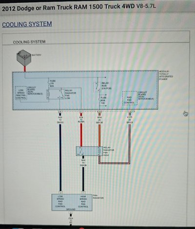
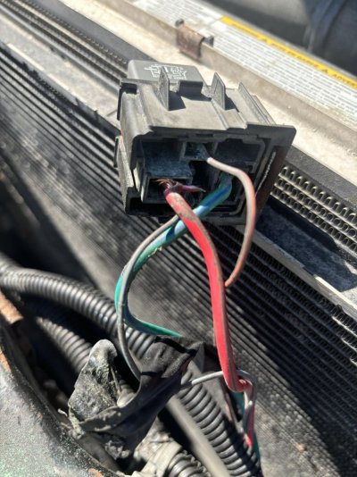
So I was able to use successfully test continuity from terminal 85 (brown/light blue wire) at the relay all the way to Pin 2 on the green plug going into the TIPM (plug is labeled as “C”). So, I guess the wire is not broken anywhere along the way, which is a good thing.
Unfortunately, I think this tells me the issue is probably inside the TIPM itself. I pulled the TIPM and opened it up. There are no obvious signs of damage, so I’m a bit unsure how to go from here or how I can fix it. I’m not too familiar on how to do the PCB trace, any pointers? How do I trace terminal 85’s ground path?
PS: My truck is a 2012 Ram 1500 5.7L HEMI.