Right intermediate shaft difference between 3.21 and 3.55 gears?

Disclaimer: Links on this page pointing to Amazon, eBay and other sites may include affiliate code. If you click them and make a purchase, we may earn a small commission.

tfoley95

Junior Member
Joined
May 17, 2024
Posts
4
Reaction score
13
Location
Northern Sconnie
Ram Year
2018
Engine
5.7
I found out the hard way recently that my 4 wheel drive didn't work. My regular mechanic said it was the passenger side intermediate shaft and C/V shaft (I had the driver's side replaced last year). That doesn't surprise me one bit as there was some slop in that joint; I just didn't think it was that bad.

Anyway, my mechanic's first option was to replace the whole diff. Yeah, that's not happening as I don't have a couple grand for a refurb unit. He told me he couldn't get just the intermediate shaft from his suppliers. He also told me the reason why is that he could only get the shaft for the 3.55 gears, and not the 3.21 gears, which is what my truck has.

After doing a bunch of reading, it seems like the intermediate shaft is the same regardless of which gearset the truck as. I'm looking for someone that might know this for sure one way or the other. After a couple of online chats with manufacturers, I'm just as confused. One says they're different, but they don't make the one I need, and another says it doesn't matter, it's the same for all.

Most of the parts listed online that specify gear ratio list 3.55, and some say 3.21/3.55 and one other that I can't remember right now. There are none that specifically reference the 3.21. So that's not really helpful.

So, does anyone know if the same intermediate shaft is used regardless of the gear ratio of the truck? I would greatly appreciate any insight anyone might be able to provide. Thank you!
 

Ken226

Senior Member
Joined
Mar 12, 2017
Posts
2,300
Reaction score
5,956
Location
Washington State
Ram Year
2013
Engine
Hemi
It's the same. None of the usual parts stores list a different part depending on axle ratio. They show the same part, regardless of ratio.


This Canadian outfit makes units that have a pretty decent reputation.

The right side shaft only:


The kit with pretty much everything:


Oreilly auto part carries it as well. The left stub shaft:


And the expensive right side shaft:

The other cheap kits on Amazon should probably be avoided. Read through the reviews and you'll see what I mean.
 
Last edited:
OP
OP
T

tfoley95

Junior Member
Joined
May 17, 2024
Posts
4
Reaction score
13
Location
Northern Sconnie
Ram Year
2018
Engine
5.7
Thanks Ken. I don't need the whole kit as the C/V shafts have been replaced and are under warranty. I'll replace the C/V shaft when I replace the intermediate shaft.

I think that maybe my mechanic just didn't want to tackle the project. :)

They also make little rubber boots that supposedly help. They won't keep the joint for 'wallowing out' over time, but they might help keep dirt and grime out of there to postpone wear.

It'll be a bit before I can get to this project. I just need it before hunting season!
 

Wild one

Senior Member
Joined
Jan 17, 2016
Posts
23,788
Reaction score
54,731
Ram Year
14 Sport
Engine
5.7
Thanks Ken. I don't need the whole kit as the C/V shafts have been replaced and are under warranty. I'll replace the C/V shaft when I replace the intermediate shaft.

I think that maybe my mechanic just didn't want to tackle the project. :)

They also make little rubber boots that supposedly help. They won't keep the joint for 'wallowing out' over time, but they might help keep dirt and grime out of there to postpone wear.

It'll be a bit before I can get to this project. I just need it before hunting season!

 
OP
OP
T

tfoley95

Junior Member
Joined
May 17, 2024
Posts
4
Reaction score
13
Location
Northern Sconnie
Ram Year
2018
Engine
5.7
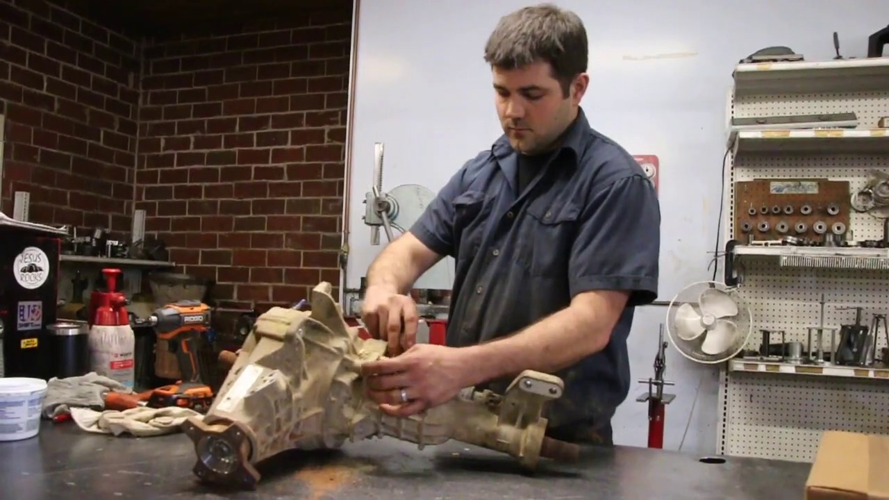
OK. I tackled this project yesterday. It took most of the day, but I work slow and don't have a ton of tools at my disposal. I purchased the right side only kit that Ken referenced above from Premium Parts. It was a complete kit with the shaft, bearings, and seal, and they are good quality parts. I would recommend it. I also bought a new C/V shaft as well. The splined cup on the end of the C/V shaft was almost smooth it was so worn. If I hadn't replaced it, this whole project would've been for nothing.

Here are the general steps I followed. I referenced this video for the working on the shaft itself. https://www.youtube.com/watch?v=zem4U9dmn6M
It's not the greatest quality, but it gives a good idea of what's involved with removing the shaft from the housing.

I learned a few things during the process, so I'll share the info so someone else may benefit. I thought about making a video of the whole thing, but didn't want to embarrass myself! :p

Step 1: Put the front of the truck up on jack stands. SAFETY WARNING!! Support the truck in several locations and do NOT just rely on your lift jack! You'll be working right under the front cross member and A-arm. If the truck falls on you, you die! Maximum safety awareness here!

Step 2: Remove the tire.

Step 3: Separate the upper control arm from the ball joint and allow the steering knuckle to go to the side. I used a pickle fork to do so and damaged the ball joint boot, so I had to go pick up a replacement.

Step 4: Remove the C/V shaft. Once I removed the spindle nut, I was able to slide the C/V shaft off the intermediate shaft first (inside joint), and then remove it from the hub. There was just enough room to take it off.

Step 5: Unplug the wiring harness from the intermediate shaft housing. I used a pick to remove the red clip from the top side and a small screwdriver to wiggle the connector free. It was a pain.

Step 6: Remove the intermediate shaft housing. There are 4 bolts securing it to the differential, and 2 (different sized) bolts securing it to the motor mount. Have plenty of ratchet extensions handy, because you'll need 'em! It's difficult to get to the upper 2 bolts securing it to the differential. I sprayed a little WD-40 in the joint before I started, and it came apart fairly easily. Do not force this. These housings are both aluminum and can break if too much force is applied. That will ruin your day!! (i broke an Envoy doing this once).

Step 7: Remove the actuator off the housing by removing 4 bolts and pulling it free. Remove the gear from the end of the shaft and set aside. You'll need it later.

Step 8: Remove the circ clip from inside the housing where the actuator came out (see above video) and then the shaft should come right out with a couple of taps. Don't let it fall, and save the circ clip.

Step 9: Remove the needle bearing from the small end of the housing. This was probably the most difficult part of the project for me. I didn't have a long enough punch to tap it out. After a few attempts with various implements, and lots of cussing and a trip to the parts store, I ended up using a Dremel and cutting it out with a small cutoff wheel. If you go this route, be very careful to not cut too deep and into the aluminum housing. The bearing is hard steel compared to the soft aluminum.

Step 10: Tap in the new needle bearing into the housing using an appropriate sized socket. Once it was in place, I packed some fresh gear into the needles.

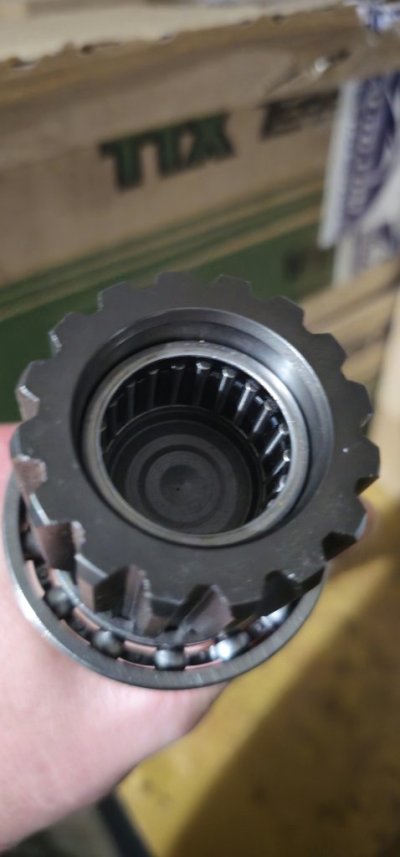
Step 11: On the new shaft, tap on the large roller bearing. I installed it with a larger chisel type implement that had a wide end. I worked my way around the bearing, tapping slowly until it was in place, making sure to only have the chisel touch the inner race. Once it was seated, the circ clip was installed. The circ clip will need to be removed from the old shaft and installed on the new one. Add grease to the roller bearing.

Step 12: Tap the small needle bearing into the cup end of the shaft. Use the appropriate sized socket to do so. Add grease to the needle bearing.

Step 13: Reinsert the shaft into the housing. It should tap back into place easily. Now reinstall the circ clip moved in step 8. Give the shaft a spin. It should spin nice and smooth.

Step 14: Install the large rubber seal on the small end of the housing. Now install the metal 'cap'. It should tap down until it's just below the lip of the housing. Tap both in slowly as to not damage them.

Step 15: Now install the rubber O ring on the small end of the shaft, and then the C clip.

Step 16: Add the gear removed earlier on the large end of the shaft and reinstall the actuator. Make sure the fork slides over the groove on the gear. I added some grease to the geared end of the shaft before I installed the gear. I also added a bit of RTV to the actuator housing to make sure it was sealed well.

Step 17: Now the completed housing assembly is ready to go back on the differential. I used a little RTV so no water/mud/salt would get into the joint between the housing the differential. Do not overtighten these bolts. They are easy to strip because the differential is aluminum.

Step 18: Plug the wiring harness in and make sure to insert the clip.

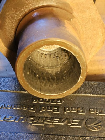
Step 19: Feed the C/V shaft from the inside of the control arm, and into the hub first. There should be enough room to insert the cup onto the intermediate shaft. This will require some 'finesse'. I made a trip to the plumbing store and bought an 1 1/2" rubber reducer. After some trimming, I installed it on the cup end of the C/V shaft. Once the steering knuckle is reconnected to the ball joint (next step), I slid the reducer toward the housing and then tightened up the hose clamp. I then ran a bead of RTV between it and the metal cap. Hopefully this will help to keep mud and grime out of the joint. Time will tell.

Step 20: Reconnect the upper control arm. This is tricky with one person, but I figured out a large C clamp is helpful here.

Step 21. Install the hub nut and tighten fully. I find a pry bar between a couple of the lug bolts helps to keep the hub from spinning while tightening.

Step 22. Install tire and tighten lug nuts.

Step 23: Take the truck for a ride and listen for strange noises etc. For me, the whole truck rode smoother, and there was no grinding noise at low speeds. Also, recently there had been a loud banging noise at highways speeds. This went away as well. If everything is copasetic with your ride, project complete!

Obligatory disclaimer: Use these steps and advice at your own risk. I am just a DIY-er that didn't want to spend a pile of cash on the repair. No implied warranty, etc etc..

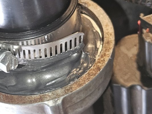
See pictures for worn C/V shaft splined cup, new C/V shaft, new C/V shaft inserted into the housing, and a closeup of RTV bead (not super pretty).
 

Attachments

  • 20240608_105310.jpg
    20240608_105310.jpg
    187 KB · Views: 12
  • 20240608_155237.jpg
    20240608_155237.jpg
    96.6 KB · Views: 9
  • 20240608_163044.jpg
    20240608_163044.jpg
    128.1 KB · Views: 11
  • 20240608_163111.jpg
    20240608_163111.jpg
    182.6 KB · Views: 12
Last edited:

Ramshig

Junior Member
Joined
Jul 4, 2016
Posts
26
Reaction score
13
Ram Year
2015
Engine
HEMI 5.7
I am going to tackle this job soon, I will be installing ttx upper, lower control arms and new CV axles as well . I have the roller bearing on the shaft and I installed the needle bearing into the cup on the large side of the shaft . My question is ,does the large and needle bearing have a certain depth it needs to go into or do you seat it all the way down . I pressed it all the way down until it stopped and I think that might be to far based on the videos I have seen , this is the bearing on the shaft it's self on the large end . Thank you for your help I might have a lot more questions once I start the job .
 

Attachments

  • 20251126_115121.jpg
    20251126_115121.jpg
    51.4 KB · Views: 1

Wild one

Senior Member
Joined
Jan 17, 2016
Posts
23,788
Reaction score
54,731
Ram Year
14 Sport
Engine
5.7
I am going to tackle this job soon, I will be installing ttx upper, lower control arms and new CV axles as well . I have the roller bearing on the shaft and I installed the needle bearing into the cup on the large side of the shaft . My question is ,does the large and needle bearing have a certain depth it needs to go into or do you seat it all the way down . I pressed it all the way down until it stopped and I think that might be to far based on the videos I have seen , this is the bearing on the shaft it's self on the large end . Thank you for your help I might have a lot more questions once I start the job .
It's a bit late to bring it back up to the surface,so you're probably stuck leaving it where it is,and seeing how it pans out and lasts.
 

Ramshig

Junior Member
Joined
Jul 4, 2016
Posts
26
Reaction score
13
Ram Year
2015
Engine
HEMI 5.7
I froze it and was able to get it flush I wasn't going to risk it . Tackling the project this weekend .
 

Wild one

Senior Member
Joined
Jan 17, 2016
Posts
23,788
Reaction score
54,731
Ram Year
14 Sport
Engine
5.7
I froze it and was able to get it flush I wasn't going to risk it . Tackling the project this weekend .
Did you watch both video's posted in this thread.Good luck,let us know how you make out. :waytogo:
 

Ramshig

Junior Member
Joined
Jul 4, 2016
Posts
26
Reaction score
13
Ram Year
2015
Engine
HEMI 5.7
Will do bro appreciate it , I have some work ahead of me that's for sure but I will have a full shop with any tool you could imagine so that will make it easier. Thanks for your help .
 

Attachments

  • 20251125_230503.jpg
    20251125_230503.jpg
    197.5 KB · Views: 4
  • 20251127_111203.jpg
    20251127_111203.jpg
    125.1 KB · Views: 3
  • 20241020_175657(1).jpg
    20241020_175657(1).jpg
    114.8 KB · Views: 2

CO-Ram

Member
Joined
Mar 19, 2019
Posts
64
Reaction score
93
Location
Aurora, Colorado
Ram Year
2016
Engine
5.7
Ramshig,
Look like you are building a kick ass ram great part's selection! Love the TTX stuff, its HD but not over the top in $. Do you have a lift or level kit on it?
 

DILLIGAF

Senior Member
Canadian Forces
Joined
May 28, 2016
Posts
5,762
Reaction score
12,308
Location
Canada
Ram Year
2012
Engine
5.7
Step 1 - throw gen 4 diff in the trash
Step 2 - Install gen 3 diff and never have to deal with that moronic design of a intermediate shaft.
 
Back
Top