I'm going to use this post to keep track of my notes for re-routing the Mirror Backup Camera Signal over to the Radio for those that have the Mirror Cam from the factory.
References:
-
bought a 5.0 uconnect head unit and need mic setup
-
get rid of back up camera in mirror?
For those that have the factory backup cam in the mirror and want to upgrade to the "Manual Mirror & Mic' setup for the RA2+ trucks. You may need the mirror harness but probably not.
Optional parts
- 911/Assist AutoDimming Mirror: - 68096091AF (sales codes req'd)
. . . or RA2 style Manual Dim Mirror w/mics: - 68102484AA
. . . (Mirror Mount Covers if Needed: Upper - 1ZA38DX9AA and Lower - 1YW11DX9AA )
- Mirror Header harness: - 68207372AB
-
2013-2016 Ram Radio Removal 6-27-16.pdf
-
2013-2016 Ram RearView Mirror (w/mics) Upgrade & Harness install 7-8-16.pdf
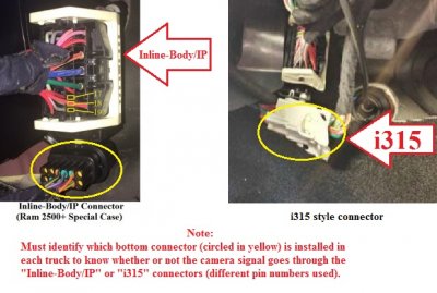
All trucks with a factory backup camera (in mirror or radio display) have the 3 camera wires going though either an i315 (pins 18,19,20) or Inline-Body/IP connector (17,18,19) near the brake pedal (footwell).
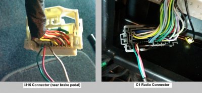
- For trucks with the camera displayed on the radio, the 3 wires go straight from the appropriate footwell connector directly to the back of the radio (pins 31,32,33).
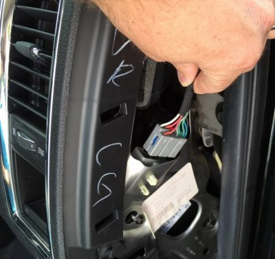
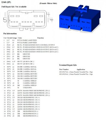
- For trucks with the camera displayed on the mirror, there is a "mirror jumper harness" that takes the 3 wires from the appropriate footwell connector over to the i340 Mirror Jumper connector (8,9,10) behind the passenger air vent. Then it goes straight up to the mirror's display.
So, for those that need to re-route the backup camera from the mirror to the radio have two options:
1) Re-route the 3 video signal wires from the i340 mirror connector (behind pass. air vent pins 8,9,& 10) over to the back of the radio (pins 31,32, & 33). You will need a custom harness with correct radio pins at a minimum to do this.
(I have located correct PN's for the pins)
or
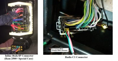
2) Re-route the 3 signal wires earlier from either an i315 (pins 18,19,20) or Inline-Body/IP connector (17,18,19) over to the radio (31,32,33) with the exact same "cab harness" Jeepguy used for his camera kit.
NOTE: If you have a 2500/3500, you may already have wires for an optional "3rd Brake light/Cargo Cam" at pins 31,32,32 that would need moved/removed from the radio connector.
Post 51 - Some basic details about the 3 Cameras/Input pins on the 8.4 (RA3/Ra4) Radios for use with the "Lockpick" or the "Customtronix Jailbreak" software.
NOTE: Dealer installed backup camera wiring using either of the two "Official" Ram kits in post 10 is completely different.
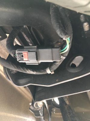
 i340 Mirror Jumper connector housing
 (Yazaki):
7282-8395-40 (Male/body side)
7283-8397-40 (female/mirror side) **
Male Terminals:
- 7114-4720-02/-08 (22-20Awg) 0.64mm
- 7114-4721-02/-08 (20-18Awg) 0.64mm
- 7114-4110-02 ___ (22-20Awg) 2.8mm
- 7114-4111-02 ___ (20-18Awg) 2.8mm
Female Terminals:
- 7116-4720-02/-08 (22-20Awg) 0.64mm (use these)
- 7116-4721-02/-08 (20-18Awg) 0.64mm (or theses)
- 7116-4110-02 ___ (22-20Awg) 2.8mm
- 7116-4111-02 ___ (20-18Awg) 2.8mm
Inline-Body/IP or i315 terminals (foot Well)
- Female 1.5mm Sockets (22-20Awg), Yazaki PN: 7116-4100-02 (Au: -08) or 7116-4780-02 (Sn)
- Female 1.5mm Sockets (18-16Awg), Yazaki PN: 7116-4101-02 (Au: -08) or 7116-4781-02 (Sn)
Radio/C1 pins (Tyco/TE Connectivity Pn's)
-
638551-3 (0.64mm sockets) @ Mouser
** I still need to piece together a schematic showing the key wiring points/differences


 View attachment 80414