How To Add Heated/Ventelated seats and Heated Wheel to Express/Tradesman

Disclaimer: Links on this page pointing to Amazon, eBay and other sites may include affiliate code. If you click them and make a purchase, we may earn a small commission.

00R/T

Senior Member
Supporting Member
Joined
Apr 18, 2016
Posts
1,278
Reaction score
808
Location
CT
Ram Year
2013
Engine
5.7 HEMI
It's probably an HD vs half ton difference.

The clockspring is a piece of cake. Once the wheel is off it's just a few bolts. You'll need to take the upper and lower shrouds off the column first.
 

69mach1

Senior Member
Joined
Apr 11, 2016
Posts
169
Reaction score
28
Ram Year
2013
Engine
Cummings 6.7
It's probably an HD vs half ton difference.

The clockspring is a piece of cake. Once the wheel is off it's just a few bolts. You'll need to take the upper and lower shrouds off the column first.

I think the clock spring is a bit more complicated to replace, not the mechanics of it, but I watched a youtube of a tech using a tech tool to watch the degrees of the clock spring to set to 0 degrees. I think it has to do with the traction control as well as how the backup camera lines turn when the wheel is turned. I wonder if you have a backup camera if you could set the truck straight with the backup camera lines straight, then swap out the clock spring and adjust it so the backup lines are straight again. it's a maybe anyway.

Chime in if I'm off the mark :favorites13:
 

69mach1

Senior Member
Joined
Apr 11, 2016
Posts
169
Reaction score
28
Ram Year
2013
Engine
Cummings 6.7
I'm guessing my job to get my heated seats working is going to be a bit more challenging as my floor harness going to the driver seat has the bare minimum wires going to the seat air bags :-( I'll be doing a lot of researching of these wiring diagrams to see just how many wires I'm going to have to run.
 

cptwing

Senior Member
Joined
Aug 14, 2014
Posts
1,446
Reaction score
494
Location
The Soviet State of Connecticut
Ram Year
2014 3500 ST DRW REG CAB
Engine
6.4l Hemi
I think the clock spring is a bit more complicated to replace, not the mechanics of it, but I watched a youtube of a tech using a tech tool to watch the degrees of the clock spring to set to 0 degrees. I think it has to do with the traction control as well as how the backup camera lines turn when the wheel is turned. I wonder if you have a backup camera if you could set the truck straight with the backup camera lines straight, then swap out the clock spring and adjust it so the backup lines are straight again. it's a maybe anyway.

Chime in if I'm off the mark :favorites13:

I had a small issue when I replaced my steering wheel once and I got the clock spring 180 degrees out. What happens is the traction control warning light comes on and the lines on the back up camera go whacko. To correct I simply rotated it 180 degrees. This cured the traction control light and the camera lines. So yes the backup camera lines are a way to know if you installed it correctly. I could be wrong but I believe you can only install it correctly or 180 out. Wish I had upgraded it then, just ordered the upgraded clock spring $250.00, Rick your killing my budget!
 
Last edited:
OP
OP
Ricks Ram

Ricks Ram

Senior Member
Joined
May 1, 2015
Posts
4,411
Reaction score
3,388
Ram Year
2014
Engine
Hemi 5.7
I'm guessing my job to get my heated seats working is going to be a bit more challenging as my floor harness going to the driver seat has the bare minimum wires going to the seat air bags :-( I'll be doing a lot of researching of these wiring diagrams to see just how many wires I'm going to have to run.

You will need to run the same wires I did for the most part. There are only a total of 9 wires that need to be connected besides hooking up the correct ignition on run power to the two pink/yellow wires in the drivers side yellow seat plug. You will need 5 wires that run from the passenger seat yellow plug to the drivers seat gray plug, two heated wheel wires from the gray drivers seat plug to the correct plug under the dash and two more wires from the drivers side gray plug to the IHS CAN + and IHS CAN-. That's pretty much it.
 

00R/T

Senior Member
Supporting Member
Joined
Apr 18, 2016
Posts
1,278
Reaction score
808
Location
CT
Ram Year
2013
Engine
5.7 HEMI
I had a small issue when I replaced my steering wheel once and I got the clock spring 180 degrees out. What happens is the traction control warning light comes on and the lines on the back up camera go whacko. To correct I simply rotated it 180 degrees. This cured the traction control light and the camera lines. So yes the backup camera lines are a way to know if you installed it correctly. I could be wrong but I believe you can only install it correctly or 180 out. Wish I had upgraded it then, just ordered the upgraded clock spring $250.00, Rick your killing my budget!


The clockspring is able to spin ~ 2 turns in either direction, so you can end up with it it at -720, -360, +360, or +720. If it rotates too far, it will destroy itself internally. The best thing to do is just make sure it's secured when installing it so it can't rotate. If you bought a new one, they come pinned so it won't rotate until you pull the pin.
 
OP
OP
Ricks Ram

Ricks Ram

Senior Member
Joined
May 1, 2015
Posts
4,411
Reaction score
3,388
Ram Year
2014
Engine
Hemi 5.7
I think the clock spring is a bit more complicated to replace, not the mechanics of it, but I watched a youtube of a tech using a tech tool to watch the degrees of the clock spring to set to 0 degrees. I think it has to do with the traction control as well as how the backup camera lines turn when the wheel is turned. I wonder if you have a backup camera if you could set the truck straight with the backup camera lines straight, then swap out the clock spring and adjust it so the backup lines are straight again. it's a maybe anyway.

Chime in if I'm off the mark :favorites13:[/QUOTE

When you purchase a Clockspring it should be locked in correct steering wheel strait alignment with a zip tie or other removable holding device. The Clockspring has a small tab that fits into the steering wheel. All you need to do is make sure the front wheels are strait when you install the Clockspring and make sure you keep it correctly oriented when you install it. If you buy a used clock spring from someone you never really know if they locked it out and didn't let it spin over or not. I got lucky and bough mine from 00/RT so I knew it would be in the correct position. He is right. Installing the Clockspring is a piece if cake as long as it's in the correct position when you install it.
 

cptwing

Senior Member
Joined
Aug 14, 2014
Posts
1,446
Reaction score
494
Location
The Soviet State of Connecticut
Ram Year
2014 3500 ST DRW REG CAB
Engine
6.4l Hemi
Adding Heated/Ventelated seats and Heated Wheel to Express/Tradesman

The clockspring is able to spin ~ 2 turns in either direction, so you can end up with it it at -720, -360, +360, or +720. If it rotates too far, it will destroy itself internally. The best thing to do is just make sure it's secured when installing it so it can't rotate. If you bought a new one, they come pinned so it won't rotate until you pull the pin.


Pretty sure when I messed mine up, I fixed it correctly as it has been fine for over a year, with zero issues. I used the backup camera to guide me, when it was wrong the lines on the camera would not follow the wheel and they would actually jump in the opposite direction.


So if you have one that you are not sure about, is the trick to spin it in one direction until it stops and then reverse that 720?
 
Last edited:

00R/T

Senior Member
Supporting Member
Joined
Apr 18, 2016
Posts
1,278
Reaction score
808
Location
CT
Ram Year
2013
Engine
5.7 HEMI
Pretty sure when I messed mine up, I fix it correctly as it has been fine for over a year, with zero issues, again I used the backup camera to guide me, when it was wrong the lines on the camera would not follow the wheel and would actually jump in the opposite direction.


So if you have one that you are not sure of is the trick to spin it in one direction until it stops and then reverse that 720?


That will get you close. You have to be careful because there are no hard stops. It stops turning when the wires inside reach their limit, so you want to be gentle about it. The issue I found was that even though I counted the number of rotations from one extreme to the other, the real center wasn't evenly between them. There also seemed to be a difference between the two units that I had.

If I had to, I probably would have guessed using that method and then tried in the truck. I didn't really want to do that unless I had to, so I ended up decoding the CAN messages coming from it. Then I was able to power it on the bench and read the angle it was reporting.
 

00R/T

Senior Member
Supporting Member
Joined
Apr 18, 2016
Posts
1,278
Reaction score
808
Location
CT
Ram Year
2013
Engine
5.7 HEMI
Wow that is slick, was that with the autoenginuity?


Sent from my iPhone using Tapatalk


No. The AE will read the steering angle, but it gets it from the BCM via the diagnostic protocol so you need to be in the truck. I just connected a CAN analyzer directly to the SCCM and looked at the raw data.
 

DeereGuy

Senior Member
Preferred Vendor
Supporting Member
Joined
Nov 9, 2016
Posts
623
Reaction score
577
Location
Pittsburgh, PA
Ram Year
2016
Engine
6.7 Cummins
Confirmed PDC information.

Seat Power Driver - PDC C5 Pin 40 - 14 AWG - 7116-4112-02
Connects to SeatCushionDriver (Yellow) Pin 1 - 7116-4112-02

Seat Power Passenger - PDC C6 Pin 2 - 14 AWG - 7116-4112-02
Connects to SeatCushionPassenger (Yellow) Pin 14 - 7116-4032

Seat Heat - PDC C7 - 16 AWG - 7116-4111-02
Connects to SeatCushionDriver(Yellow) Pin 8 - 7116-4111-02

Seat Heat - PDC C7 - 16AWG - 7116-4111-02
Connects to SeatCushionDriver(Yellow) Pin 7 - 7116-4111-02

Rear Heat - PDC C7 - 20AWG - 7116-4100-02
Connects to --> I haven't traced this one out yet.

I figured these out by cross referencing PDC repair kit part numbers against other yazaki connectors repair kit numbers of which I knew what the terminal numbers were. I then ordered two sets of PDC repair kits, and then physically verified that the terminals that I listed matched the repair kit terminals.

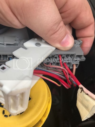
Also, the CAN IHS BUS connects to a two pin connector. It's part number is 5-2138650-1 and corresponding terminals 5-963715-1. Does anyone know how exactly this connector plugs in? Is it housed in a larger connector with the other CAN IHS Bus connectors or does it plug in by itself? I haven't had a chance to look under by dash and see where it actually plugs in based on the diagrams I got from tech authority and Rick.

Rick or 00R/T can one of you verify that the terminal #'s that I listed for the seat side are correct? Thanks.

I roughed in wiring from the PDC this afternoon. I have updated the above post with all of the correct PDC terminal numbers. This was a lot easier than I expected. I had all fuses and relays in my PDC.

Basically you:

1. Disconnect your battery.
2. I drilled a 3/4 inch hole in the clutch delete plate and put a 1/2 inch rubber grommet in it.
3. I removed the PDC from its mounts and gently moved it so I could see the connectors below it.
4. Run your wires through the clutch delete plate to the PDC.
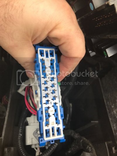
5. Remove the connector from the bottom of the PDC by squeezing the tab on the end of the handle and opening it up.
6. There is a white terminal lock on the front of the connector. You will need to gently pry up on the white lock so that the terminals can be inserted.
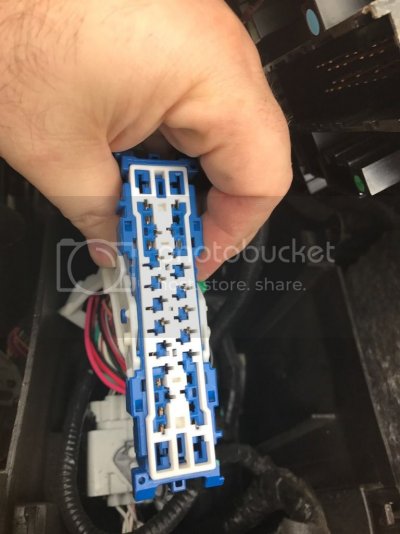
IMG_0595_zpsg3hvnrbk.jpg

7. Insert the terminal in the correct location and reinsert the terminal lock.
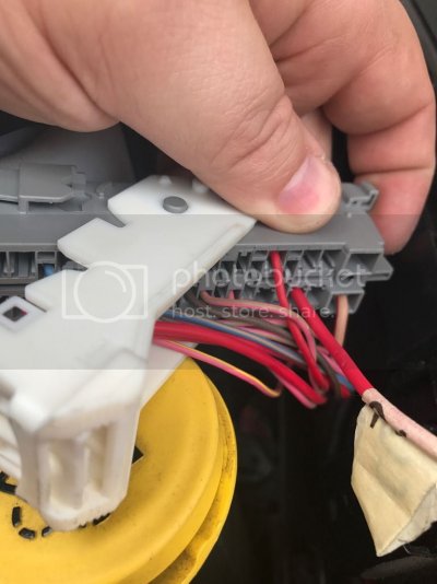
IMG_0593_zpscnlhgiv8.jpg

(Note this shows the C6 connector with the wire pinned into slot 3. It's suppose to be in slot 2. I got to figure out how to depin the connectors also lol)

8. Rinse and repeat for each PDC connector that needs a terminal.
9. I then put the wires in 3/8 inch split wire loom which fits perfectly in the 1/2 grommet that I put in the clutch delete plate.
10. Replace the PDC.
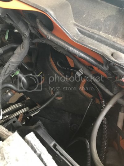
IMG_0596_zpsjajpovni.jpg
 

DeereGuy

Senior Member
Preferred Vendor
Supporting Member
Joined
Nov 9, 2016
Posts
623
Reaction score
577
Location
Pittsburgh, PA
Ram Year
2016
Engine
6.7 Cummins
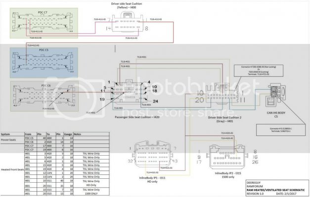
I've been working on putting a schematic together that incorporates Rick's and 00R/T's work and the research that I have done into the same format that cptwing and mpgrimm2 has done for the RA4 conversion. Here is my first draft. I'll keep making updates to it over the next several days.

HeatedSeatSchematics_zpsltw019xz.jpg
 
Last edited:

12sportmc

Senior Member
Joined
Oct 21, 2016
Posts
797
Reaction score
356
Location
NC
Ram Year
2014
Engine
5.7 Hemi
I roughed in wiring from the PDC this afternoon. I have updated the above post with all of the correct PDC terminal numbers. This was a lot easier than I expected. I had all fuses and relays in my PDC.


Basically you:


1. Disconnect your battery.

2. I drilled a 3/4 inch hole in the clutch delete plate and put a 1/2 inch rubber grommet in it.

3. I removed the PDC from its mounts and gently moved it so I could see the connectors below it.

4. Run your wires through the clutch delete plate to the PDC.

5. Remove the connector from the bottom of the PDC by squeezing the tab on the end of the handle and opening it up.

6. There is a white terminal lock on the front of the connector. You will need to gently pry up on the white lock so that the terminals can be inserted.


IMG_0595_zpsg3hvnrbk.jpg


7. Insert the terminal in the correct location and reinsert the terminal lock.


IMG_0593_zpscnlhgiv8.jpg


(Note this shows the C6 connector with the wire pinned into slot 3. It's suppose to be in slot 2. I got to figure out how to depin the connectors also lol)


8. Rinse and repeat for each PDC connector that needs a terminal.

9. I then put the wires in 3/8 inch split wire loom which fits perfectly in the 1/2 grommet that I put in the clutch delete plate.

10. Replace the PDC.


IMG_0596_zpsjajpovni.jpg


So if going this route to the PDC does this eliminate the need to add in a relay? Or is that still required? Also have you been able to locate the CANBUS connection to pin vs tapping it at the OBD port?


Sent from my iPhone using Tapatalk
 

DeereGuy

Senior Member
Preferred Vendor
Supporting Member
Joined
Nov 9, 2016
Posts
623
Reaction score
577
Location
Pittsburgh, PA
Ram Year
2016
Engine
6.7 Cummins
So if going this route to the PDC does this eliminate the need to add in a relay? Or is that still required? Also have you been able to locate the CANBUS connection to pin vs tapping it at the OBD port?


Sent from my iPhone using Tapatalk

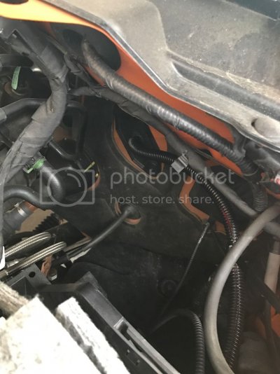
Yes no need to add the relay. It's already in the PDC. The can bus is up in the dash by the brake pedal. I spied it today but didn't get a picture. I'll try to get one tomorrow.
 

12sportmc

Senior Member
Joined
Oct 21, 2016
Posts
797
Reaction score
356
Location
NC
Ram Year
2014
Engine
5.7 Hemi
Yes no need to add the relay. It's already in the PDC. The can bus is up in the dash by the brake pedal. I spied it today but didn't get a picture. I'll try to get one tomorrow.


Awesome. That's what I was thinking to on the PDC. Where did you order the repair kits from to get the right pins?


Sent from my iPhone using Tapatalk
 

DeereGuy

Senior Member
Preferred Vendor
Supporting Member
Joined
Nov 9, 2016
Posts
623
Reaction score
577
Location
Pittsburgh, PA
Ram Year
2016
Engine
6.7 Cummins
Awesome. That's what I was thinking to on the PDC. Where did you order the repair kits from to get the right pins?


Sent from my iPhone using Tapatalk

You can order the terminals using the part numbers above from nexlec.com.
Nexus Electronics
 

12sportmc

Senior Member
Joined
Oct 21, 2016
Posts
797
Reaction score
356
Location
NC
Ram Year
2014
Engine
5.7 Hemi
Thanks @deereguy. Thinking about putting one together with measurements and making a few extra for others that may want to tackle this mod but might not have the wiring experience. Maybe a few others on here that also pioneered the 8.4 harnesses would also be interested in doing something like that.


Sent from my iPhone using Tapatalk
 

Ruiner

Senior Member
Joined
Jul 6, 2013
Posts
199
Reaction score
74
Location
Alberta
Ram Year
2012
Engine
Cummins
I can't say they will and be 100% sure they will but mine did. The member with the truck that didn't had a 2012. My truck is a 14 and all of the buttons on the LEDs lit up exactly as they are supposed to even before I added the codes. That is the whole reason I waited to add the codes until I was able to see if it would work without them for people who are unable to add the code. Your instalation should be plug and play as long as you get the switch panel if you have a Bighorn.

That's me.
I still haven't gotten them to light up.

I have ideas why, as unplausible as it seems, but it might be easier to call FCA and get them to add the codes to my VIN then reflash the truck.
 
OP
OP
Ricks Ram

Ricks Ram

Senior Member
Joined
May 1, 2015
Posts
4,411
Reaction score
3,388
Ram Year
2014
Engine
Hemi 5.7
I just checked your profile and saw that your in Canada. I was hoping you were closer so I could possibly add the codes to your truck with my scan tool. Hopefully the dealer can get the codes added for you.
 
Top